Mounting the IDU-C Chapter 3
WinLink 1000 User Manual Release 1.9.40 3-11
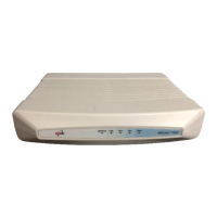
The Indicator LEDs (Item A in Table 3-1 above) are shown in more detail below:
Figure 3-14: IDU-C Front Panel LEDs
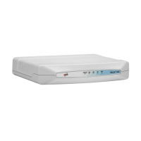
The IDU-E Front Panel LEDS look like this and are functionally the same as the IDU-C LEDs.
Figure 3-15: IDU-E Front Panel LEDs
The purpose of the LEDs is shown in Table 3-2 below:
G Primary 3 pin Power Connector
Standard 3 pins in line power connector, see Table B-8.
H Secondary 3 pin Power Connector
I Grounding Lug Use the lug supplied.
J Rack mounting holes
K Detachable Rack mounting brackets
L 0, 4, 8 or 16 E1/T1 Ports See Table B-5.
M Standby Port Hot Standby ready: HSB cable socket, see Table B-6.
Table 3-2: IDU-C and IDU-E/R Front Panel LEDs
Name Color Function
IDU
Green
Blinking Green
Red
Blinking Orange
IDU operational
During power-up only
Failure
During power-up; continues if ODU fails to load IDU firmware.
Also, when using an IDU-C to replace a PoE device in which case all other LEDs off.
ODU
Green
Red
ODU-to-IDU communication link is operating
ODU-to-IDU communication link is disrupted
AIR I/F
Green
Orange
Red
Wireless link is synchronized
During installation mode; also signals software mismatch on some identical ODUs
Wireless link lost synchronization
Table 3-1: Components of an IDU-C front panel
Key Label Remarks
 Loading...