Getting started
R&S
®
LCX Series
30User Manual 1179.2260.02 ─ 02
1 2
345678910
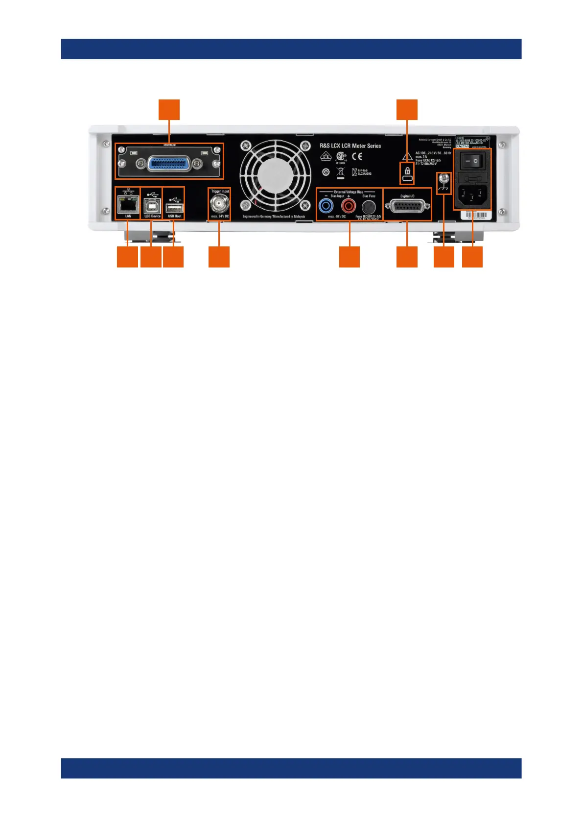
Figure 4-6: R&S
LCX rear panel
1 = IEEE-488 interface, see "IEC 625/IEEE 488" on page 30
2 = Kensington lock, see "Kensington lock" on page 30
3 = AC power connector and power switch, see "AC power supply" on page 30
4 = Ground terminal, see "Ground terminal" on page 31
5 = D-sub connector, see "Digital I/O" on page 31
6 = Bias connectors and fuse holder, see "External Voltage Bias" on page 31, "BIAS Fuse" on page 31
7 = Trigger input connector, see "Trigger Input" on page 31
8 = USB host connector, see "USB A" on page 29
9 = USB device connector, see "USB B" on page 31
10 = Ethernet (LAN) interface connector, see "LAN" on page 31
IEC 625/IEEE 488
Option: R&S NG-B105
General purpose interface bus (GPIB) interface to connect a computer for remote con-
trol of the R&S LCX.
See "Establishing the GPIB remote control connection" on page 158.
Kensington lock
Flat key security slot to prevent the instrument from removal.
The locking system consists of a small, metal-reinforced hole with a metal anchor and
a rubberized metal cable that is secured with a key lock. The loop at the end of the
cable allows you to tie the unit to a fixed object.
AC power supply
Mains power supply with power switch, fuse holder and IEC socket.
●
Mains power switch:
Switch for connecting and disconnecting the internal power supply from the power
source, see Chapter 4.1.10, "Switching on or off", on page 25.
●
Fuse holder
Socket for the fuse securing the line voltage. Depending on the power supply sys-
tem, the corresponding fuse must be plugged before connecting to power. See
"Connecting to power" on page 21.
●
IEC socket
Instrument tour

 Loading...


