Serial Bus Analysis
R&S
®
RTC1000
128User Manual 1335.7352.02 ─ 02
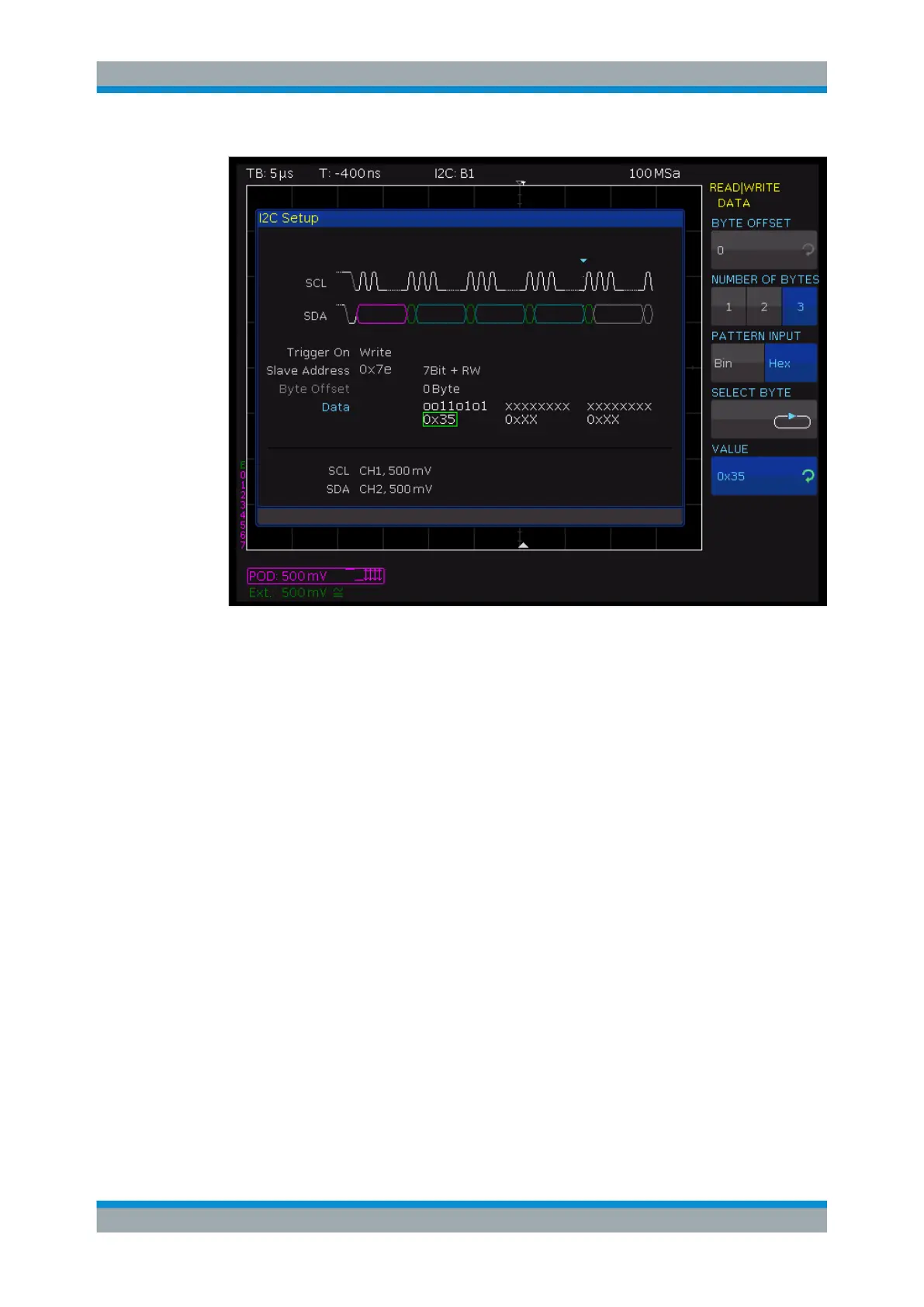
Figure 11-5: Read/Write trigger menu
"MASTER"
Toggles the trigger condition between read and write access. The 8th
bit of the first data unit (depending on the address length) is used to
distinguish between read and write access. The selected condition is
displayed in the I
2
C settings window.
"ADDRESS
LENGTH"
Defines the address length, and thus the maximum number of slave
addresses. For a 7-bit address length, the maximum number of avail-
able addresses is 112. The 10-bit addressing mode is downward
compatible with the 7-bit addressing mode by using 4 of 16 reserved
addresses and can be used simultaneously. For a 10-bit address
length, a total of 1136 addresses (1024 + 128 - 16) is available. The
highest 10-bit address is 1023 (0x3FF). The selected address length
is displayed in the I
2
C settings window.
"SLAVE
ADDRESS"
Sets the address of the slave the master communicates with. Use the
UNIVERSAL knob to select the address to be triggered.
"DATA"
Trigger on a specific address and/or data pattern. See "DATA"
on page 128.
DATA
"DATA" triggers on specific data in addition to the address. You can trigger on clearly
defined data bytes (color cyan) within the transmission, allowing you to filter out irrele-
vant transmissions. You can trigger on up to 24 bit (3 bytes) of data. An offset of 0 to
4095 to the address is allowed.
I
2
C Bus (Option R&S RTC-K1)