Serial Bus Analysis
R&S
®
RTC1000
137User Manual 1335.7352.02 ─ 02
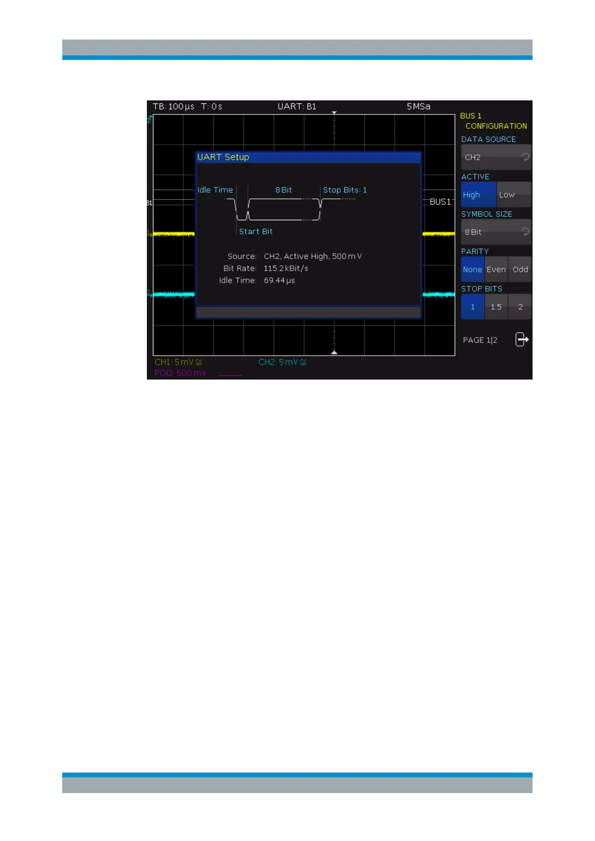
Figure 11-11: Page 1|2 UART bus setup menu
DATA SOURCE
Selects the channel which is connected to the data line.
ACTIVE
Determines if the data transferred are active high (high = 1) or active low (low = 1). For
RS-232, choose active low.
SYMBOL SIZE
Selects a value between 5 bit to 9 bit for the bits that form a symbol.
PARITY
Parity bits are used to detect errors during a transmission:
"None"
No parity bits
"Even"
If the number of ones in a specific set of bits is uneven (without parity
bit), the parity bit is set to "1".
"Odd"
If the number of ones in a specific set of bits is uneven (without parity
bit), the parity bit is set to "1".
STOP BITS
Sets the number of stop bits: 1 or 1.5 or 2 stop bits are possible.
BIT RATE, USER
The bit rate defines how many bits are sent per second. To select a standard bit rate,
use "BIT RATE". To define a customized rate, use "USER".
UART/RS-232 BUS (Option R&S
RTC-K2)