Serial Bus Analysis
R&S
®
RTC1000
140User Manual 1335.7352.02 ─ 02
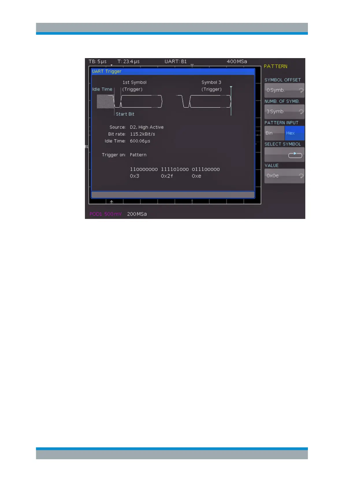
Figure 11-13: Trigger menu to trigger on a data pattern
"SYMBOL
OFFSET"
Selects the number of irrelevant symbols that proceed the pattern.
Any value between 0 to 4095 symbols after the start bit can be
entered.
"NUMB. OF
SYMB."
Selects the number of symbols included in the pattern, the pattern
size. The symbol length is configured in the bus configuration.
"PATTERN
INPUT"
See "PATTERN INPUT" on page 129.
PARITY ERROR
Triggers on a parity error.
FRAME ERROR
Triggers on a frame error.
BREAK
Triggers on a break. The condition is fulfilled if a stop bit does not succeed a start bit
within a specified time period.
11.5.3 UART Decode Results
Certain portions of the UART messages are displayed in color to distinguish between
the different elements:
●
White: Start / End of complete frame
UART/RS-232 BUS (Option R&S RTC-K2)