6-8 Mains and Supply Voltage Connection Rexroth EcoDrive Cs Drives
DOK-ECODR3-DKC**.3-CS*-PR02-EN-P
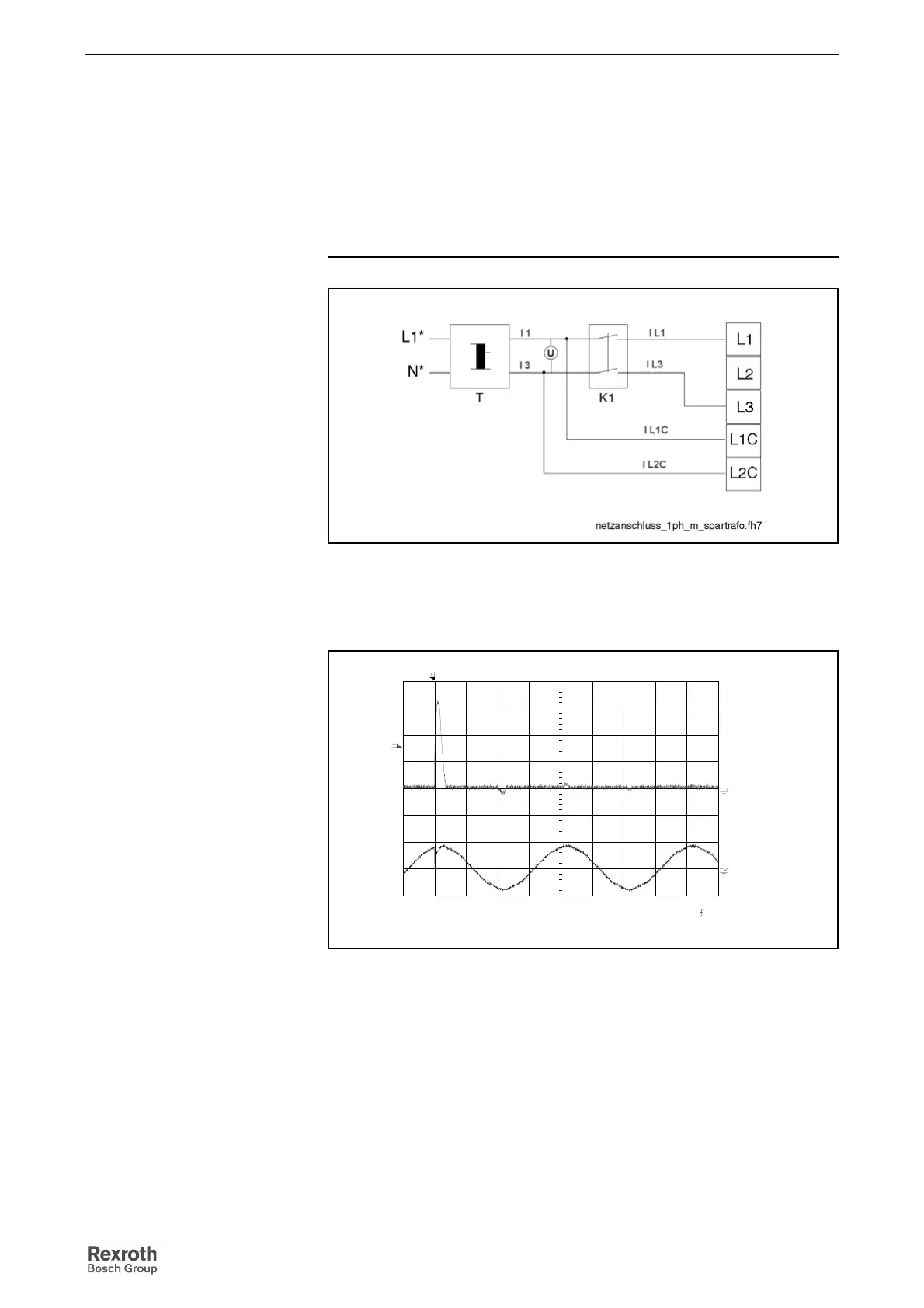
Curve of Inrush Current with Single-Phase Operation
According to the kind of connection (single-phase or three-phase), the
inrush current is of different intensity. The figure below illustrate the test
setup and the basic time flow of the inrush current.
Note: As the curve of the inrush current is not sinusoidal, make sure
you have the appropriate measuring devices when measuring
the current!
Fig. 6-8: Test setup for voltage measurement with single-phase connection
(U = 230 V)
The measurements below illustrate the basic curve of the inrush current
with completely discharged DC bus when switching on the mains voltage.
Stopped
2003/07/03 13:01:30 5ms/div
(5ms/div)
NORM:200kS/s
CH1=100mV
DC 1:1
CH4=20V
DC 10:1
=Filter=
Smoothing : OFF
BW : FULL
=Offset=
CH1 : 0.004V
CH2 : 0.003V
CH3 : 0.000V
CH4 : 0.0V
=Record Length=
Main : 10K
Zoom : 10K
=Trigger=
Mode : NORMAL
Type : EDGE CH1
Delay : 0.0ns
Holdoff : MINIMUM
Fig. 6-9: I L1C (upper curve) and mains voltage or transformer output (lower
curve) when switching on (time basis: T = 5 ms/div)
I L1C when switching on control
voltage
Courtesy of CMA/Flodyne/Hydradyne ▪ Motion Control ▪ Hydraulic ▪ Pneumatic ▪ Electrical ▪ Mechanical ▪ (800) 426-5480 ▪ www.cmafh.com