Rexroth EcoDrive Cs Drives Electrical Connections 5-19
DOK-ECODR3-DKC**.3-CS*-PR02-EN-P
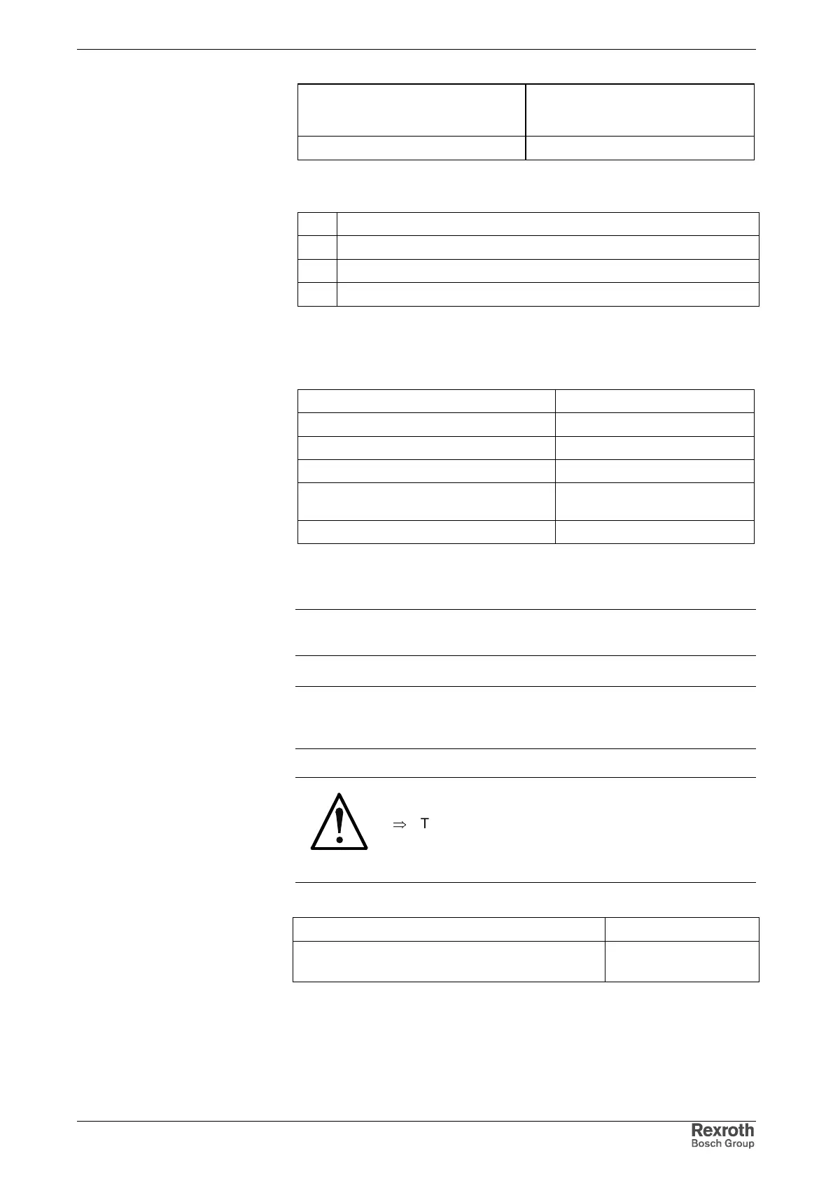
Max. cross section
single-core
[mm²]
Cross section in AWG
gauge No.
0,25 - 0.5 23 - 20
Fig. 5-39: Connection cross section
4 holding brake-
3 holding brake+
2 +24V_ext_brake
1 0V_ext_brake
Fig. 5-40: Holding brake and voltage connection
Load Capacity of the BR+, BR- connection:
max. switching voltage DC 36 V
max. switching current DC 1 A
max. continuous current DC 1 A
voltage drop electronic contact 100 mV
guaranteed number of switching operations unlimited (wear-resistant
electronic contact)
short-circuit and overload protection present
Voltage connection for brake
Note: The motor holding brake is not supplied by the drive controller.
Observe the data of the motor holding brake.
Note: It is impossible to loop through the voltages to other drive
controllers. Other drive controllers have to be connected to the
voltage source in star-shaped form.
CAUTION
Risk of damage!
⇒
The maximum allowed current load of the terminal
connectors for the voltage supply of the brake and
the control voltage supply must also be observed in
the case of a short circuit.
max. voltage at X5_3.1 referring to X5_3.2: 36 V
current consumption at X5_3.3 and required supply
voltage:
see chapter Holding
Brake
on page 8-29
Connection Cross Section
BR+, BR-
Connection
Courtesy of CMA/Flodyne/Hydradyne ▪ Motion Control ▪ Hydraulic ▪ Pneumatic ▪ Electrical ▪ Mechanical ▪ (800) 426-5480 ▪ www.cmafh.com