5-24 Electrical Connections Rexroth EcoDrive Cs Drives
DOK-ECODR3-DKC**.3-CS*-PR02-EN-P
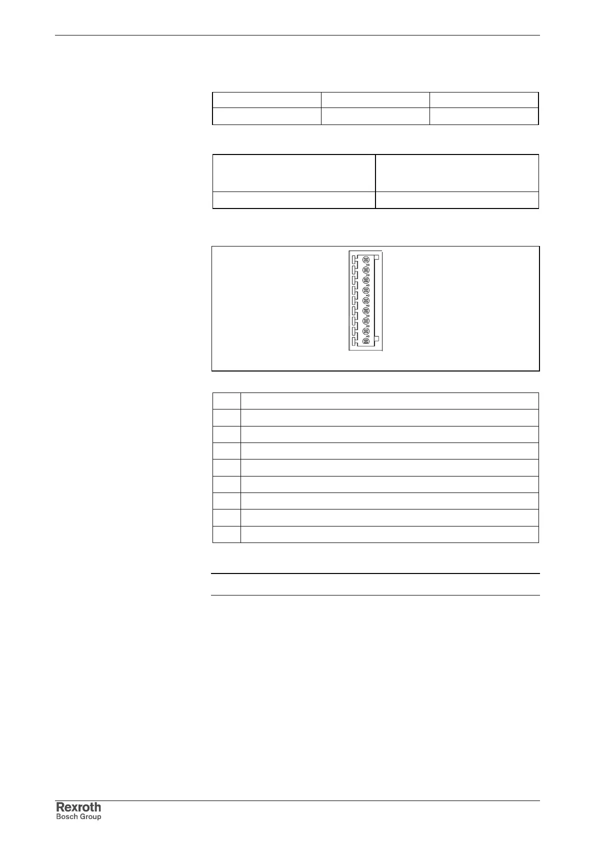
X5_4, Analog and Digital I/Os
Type Number of poles Type of design
spring tension 9 socket on connector
Fig. 5-46: Design
Max. cross section
single-core
[mm²]
Cross section in AWG
gauge No.
0,25 - 0.5 23 - 20
Fig. 5-47: Connection cross section
ana_para_anschluss.FH7
9
8
7
6
5
4
3
2
1
IN11
IN10
IN9
IN8
OUT6
OUT5
OUT4
OUT3
OUT2
9 IN11 (input)
8 IN10 (input)
7 IN9 (input)
6 IN8 (input)
5 OUT6 (output)
4 OUT5 (output)
3 OUT4 (output)
2 OUT3 (output)
1 OUT2 (output)
Fig. 5-48: Pin configuration
Note: Default configuration: see Functional Description of firmware.
The inputs IN8, IN9 and IN10, IN11 can optionally be configurated as
analog inputs (see Functional Description of firmware).
Input working voltage range between analog inputs:
±10V
Analog/Digital converter: 12 bits
Design
Connection Cross Section
Pin Configuration
Voltage Range between Analog
Inputs
Resolution
Courtesy of CMA/Flodyne/Hydradyne ▪ Motion Control ▪ Hydraulic ▪ Pneumatic ▪ Electrical ▪ Mechanical ▪ (800) 426-5480 ▪ www.cmafh.com