Rexroth EcoDrive Cs Drives Electrical Connections 5-27
DOK-ECODR3-DKC**.3-CS*-PR02-EN-P
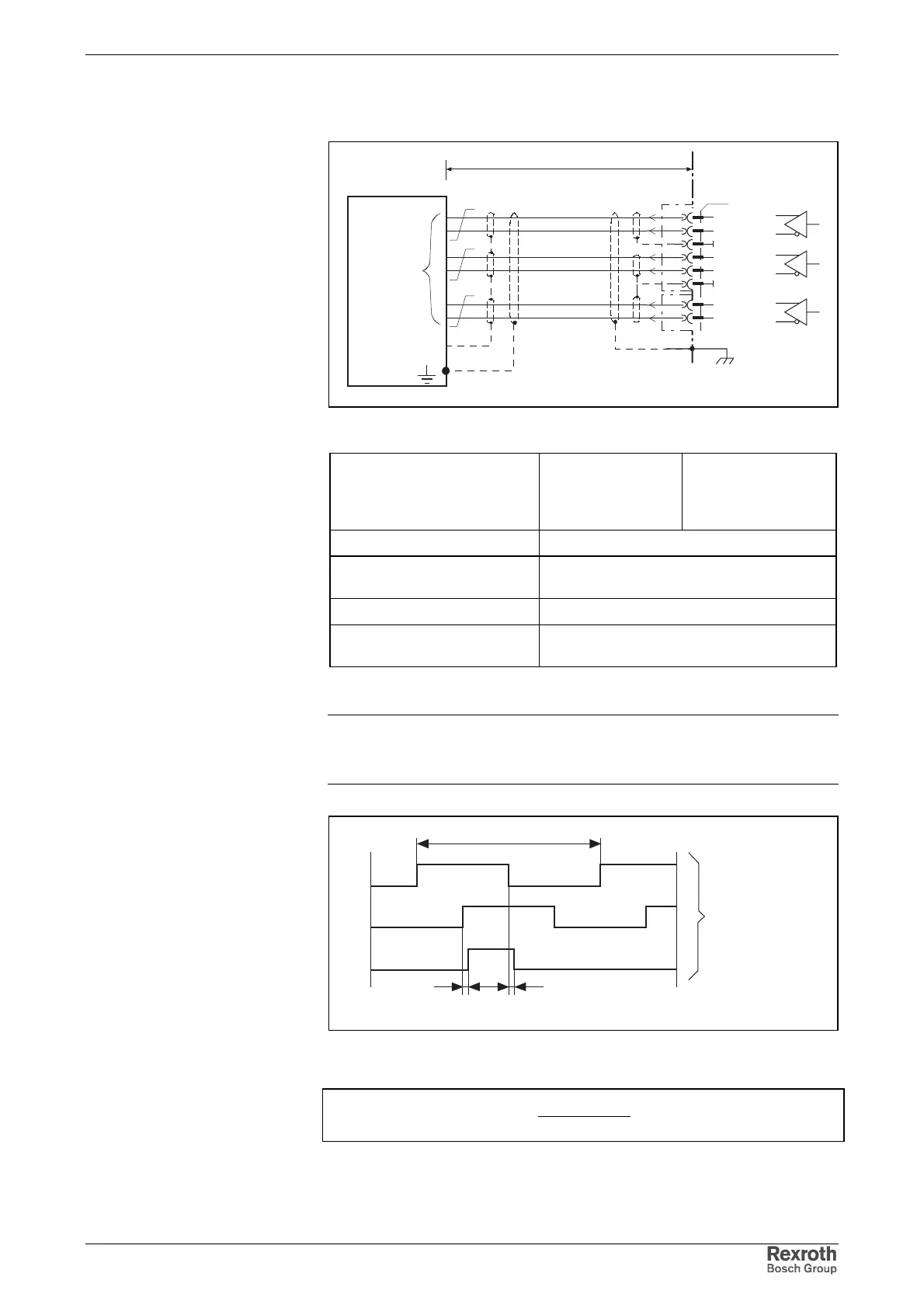
Incremental Encoder Emulation
emu_inkr_anschluss.FH7
CNC
0V
ext
1
IgsUA1+
2
IgsUA1-
3
0V
4
IgsUA2+
5
IgsUA2-
6
0V
7
IgsUA0+
8
IgsUA0-
X7
length l
positioning
interface
-incremental-
Fig. 5-52: Connection of incremental actual position value output
Output voltage:
High
Low
min.
2.5 V
0 V
max.
5 V
0.5 V
max. output current I
out
I20I mA
max. load capacitance
between output and 0 V 10 nF
max. output frequency f 1 MHz
Overload protection Outputs may not be short circuited. Danger of
damage!
Fig. 5-53: Differential outputs
Note: The differential outputs correspond to RS422 specs.
A termination resistor is required an the controller side, if it is
not present then add an external resistance of 150 - 180 Ohm.
one line
t1
UA1
UA0
UA2
Square-wave pulse
looking at the motor
shaft and in
clockwise direction
SV0201F1.FH7
t1 < 50 ns
t1
Fig. 5-54: Signal for incremental actual position value output
n
sRevolution
QuantityLine
f •=
f: output frequency
n: velocity (rotary)
Fig. 5-55: Calculating the output frequency f
Connection
Incremental encoder emulation
Differential outputs incremental
encoder emulation
Signal for incremental actual
position value output
Output frequency f
Courtesy of CMA/Flodyne/Hydradyne ▪ Motion Control ▪ Hydraulic ▪ Pneumatic ▪ Electrical ▪ Mechanical ▪ (800) 426-5480 ▪ www.cmafh.com