SYNAX200 Set-Up Interfaces 10-3
DOK-SYNAX*-SY*-07VRS**-PR01-EN-P
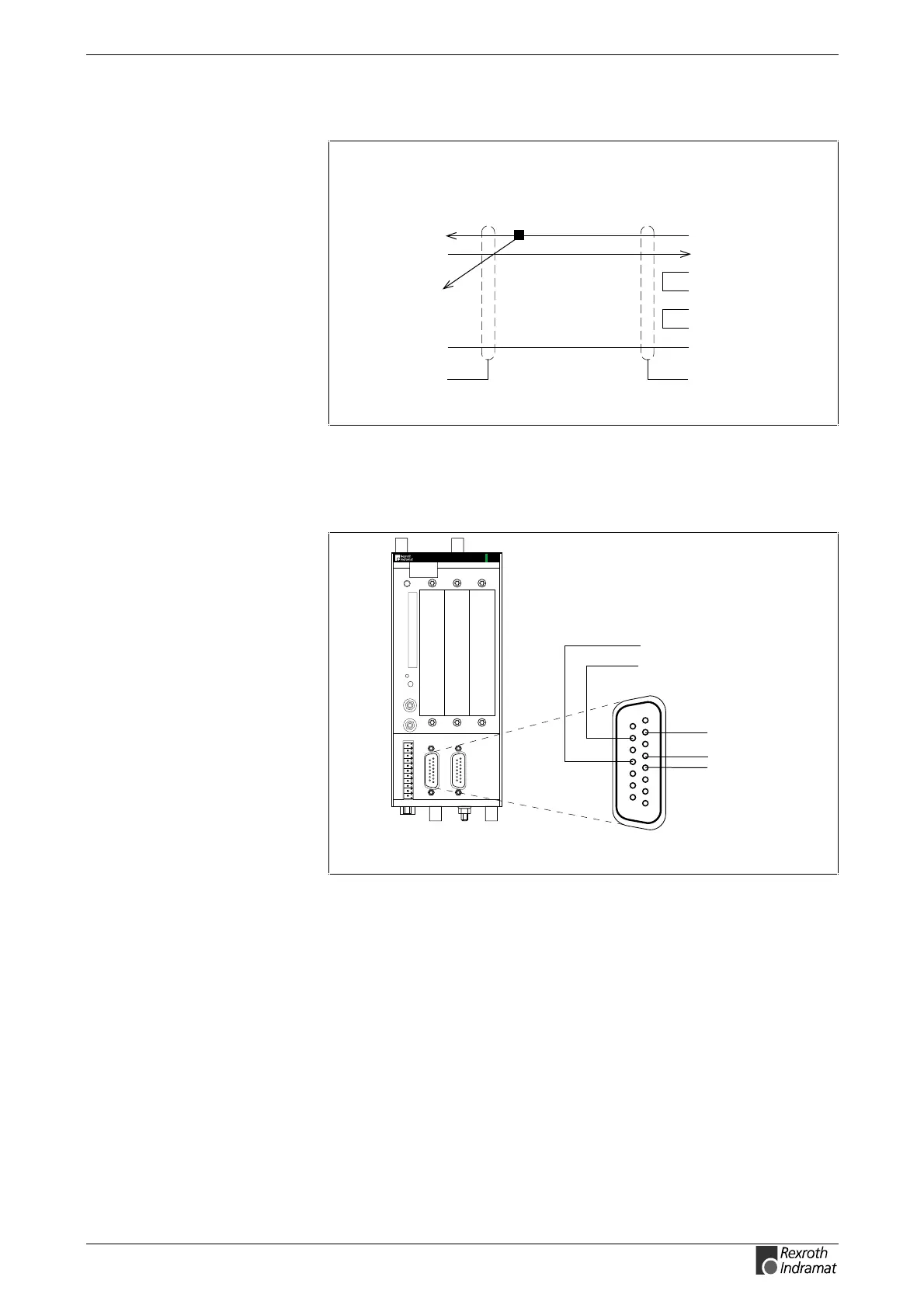
The cable from interface module to PC is constructed as follows:
3
2
4
9-pin, bushing
TxD
RxD
DTR
RS232 cable from PC to converter
SY7PR060.FH7
8
7
CTS
RTS
5
GND
6DSR
PSM-EG.: D-Sub
3
2
4
TxD
RxD
DTR
8
7
CTS
RTS
5
GND
6DSR
9-pin, bushing
PC side: D-subminiature
connector
housing
connector
housing
Fig. 10-4: RS232 cable from PC to converter
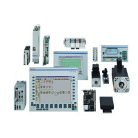
RS485 Connection of the PPCs
SY7PR110.FH7
PPC-R02.2
PROG
X10
RECO
0 V
+ 5 V
GND
RS485-
RS485+
X10 or X16
1
4
5
7
8
15
12
10
9
Fig. 10-5: RS485 connection of the PPC
RS485 Connection of the Interface Module
On RS485, the D(A) and D(B) are twisted in pairs and connected. GND is
also connected. These can be connected to the interface module using
either screw-in clamps or male D-subminiature 9-pin connectors (bushing
is on the module).
Connector: D(A) data negative pin 8, D(B) data positive pin 3, GND pin2.
Cable converter <->PC