10-4 Set-Up Interfaces SYNAX200
DOK-SYNAX*-SY*-07VRS**-PR01-EN-P
8
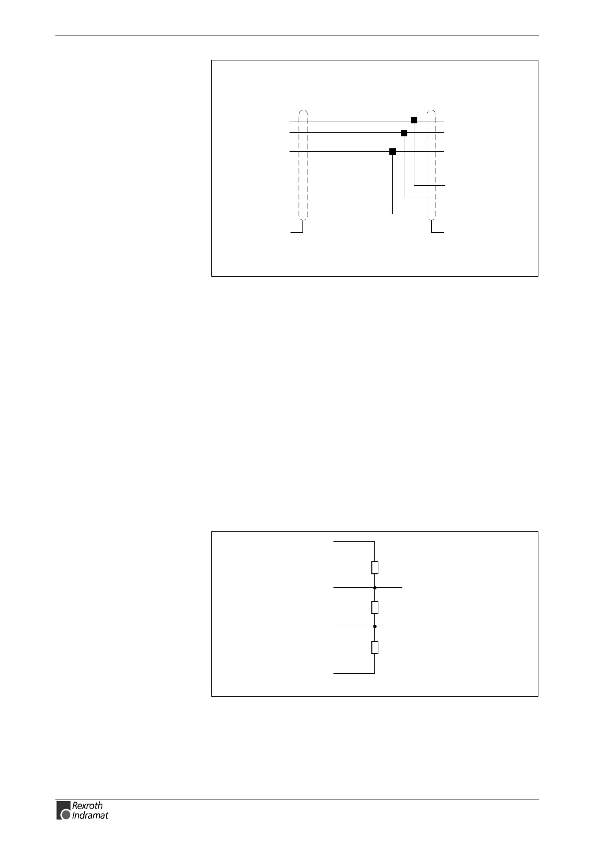
3
9-pin, pins
D(A)
D(B)
RS485 cable between PSM-EG and PPC
SY7PR062.FH7
2GND
PSM-EG.: D-subminiature
5
4
D(A)
D(B)
15-pin, pins
PPC: D-subminiature
7GND
5D(A)
4D(B)
7GND
D(A) and D(B)
twisted in pairs
D-sub15 bushing
to the next PPC
connector
housing
connetor
housing
RS485-
RS485+
Fig. 10-6: RS485 cable between converter PSM-EG and PPC
RS485 Cable
The RS485 bus cable should be shielded and twisted in pairs. The
diameter should equal at least 0.22mm
2
, with a characteristic impedance
of 100-120
Ω.
The shield is applied at both ends of the transmission path. If
equipotential currents are expected, then one side is directly grounded
and the other is grounded via a 15nF capacitor.
Bus Matching
The bus matching must be effected on both bus ends. If a bus end is
constructed with RS485 coupler above, then the bus matching in the
coupler can be connected via switch in the coupler.
Power supply of the bus machting can also be received by the PPC.
0 V
+ 5 V
GND
RS485-
RS485+
SY7PR111.FH7
390 Ω
150 Ω
390 Ω
Fig. 10-7: Power supply of the bus matching via PPC