SYNAX200 Determing Drive and System Configurations 1-7
DOK-SYNAX*-SY*-07VRS**-PR01-EN-P
SY7PR048.FH7
high-resolution
master axis
encoder interface
DEA
digital input
and output
interface
DZF
high-resolution
gear-tooth
encoder interface
DFF
high-resolution
master axis
encoder interface
DEA04/
DEA08
DZF
DFF
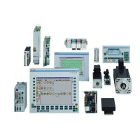
Plug-in modules functionally assigned
to the drives:
gear-tooth encoder
rack-and-pinion
encoder
SERCOS
interface
Plug-in modules functionally assigned
to the PPC control unit:
e.g. PLC
fiber optic cable
travel limit switch
referencing switch
measuring input
Interface module assigned to either the drive
or the PPC control unit:
DSS
high-resolution
digital servo
feedback
interface
motor feedback
with MHD, MKD
GDS 1.1
GDS 1.1
X4
X4
master axis
position SSI-
output interface
DSA
SSI
EnDat/SSI
encoder
interface
Weg
SSI
SSI
DAG
Weg
DLF
high resolution
position interface
DLF
DEF
position interface for
square-wave signals
DEF
Weg
motor feedback or
master axis encoder
EnDat
DAE
analogue interface
with position value
output (only ELS5)
DAE
+/- 10V analog
incremental
encoder emulation
DEA
digital input
and output
interface
DEA05/
DEA06/
DEA09/
DEA10
e.g. PLC
drive cam
Fig. 1-7: Functional assignment of the drive plug-in modules with SYNAX200
system configuration