SYNAX200 Determining the Control-Related Plug-In Cards 6-5
DOK-SYNAX*-SY*-07VRS**-PR01-EN-P
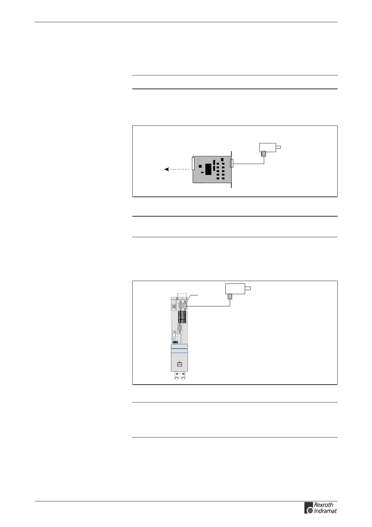
Incremental Encoder with Sinusoidal Signals 1Vss
It is also possible to connect a real master axis using an incremental
encoder with sinousoidal signals 1Vss.
Note: Use only encoders with binary line numbers (2
n
).
In this case use encoder interface DLF.
SY7PR112.FH7
incremental encoder with
sinusoidal signals 1Vss
DLF
master axis position
in the slot of a
DKR/HDS
Fig. 6-8: Incremental encoder with sinousoidal signals 1Vss
Note: There is no zero impulse evaluation, that means that the
master axis position has no absolute reference
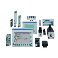
The incremental encoder with sinousoidal signals 1Vss is connected to
the second interface X8.
Barcode
0
1
2
3
4
5
6
7
8
9
0
1
2
3
4
5
6
7
8
9
H1
S1
S3
S2
Barcode
Typenschild
123456789 1234
11121314 15161718
5678
1234
5678
XE2
XE1
L+
L-
L1
L2
L3
A1
A2
A3
Read and follow
Instructions for Electrical Drives"
manual,
DOK-GENERL-DRIVE******-SVS...
DANG
High oltage.
Danger of electrical shock.
Donot touch electrical connec tions
for
5 minutes after switching
x8
SY7PR113.FH7
incremental encoder with
sinusoidal signals 1Vss
Fig. 6-9: incremental encoder with sinousoidal signals 1Vss
Note: The evaluation of the zero impulse of ECODRIVE03 is
parameterizable. If the zero impulse is evaluated, the master
axis position changes immediately when registrating the zero
impulse. This must be considered for application.
DIAX03, DIAX04
ECODRIVE03