and
Adjustment
4.14 COPY ADJUSTMENTS PRINTING/SCANNING
You need to perform the adjustment after you do a Memory All Clear, and after you
replace or adjust any of the following parts.
First or second scanner
Lens Block
Scanner Motor
Polygonal Mirror Motor
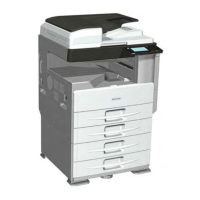
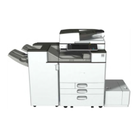
Paper Tray
Paper Side Fence
For detailed explanations about how to access and use the SP modes, see Section 5.
4.14.1 PRINTING
Make sure the paper is installed correctly in each paper tray before you start these
adjustments.
Use the Trimming Area Pattern SP5-902, No. 10 (D160/D161/D170) or SP2-109, No.14
(D158/D159) to print the test pattern for the printing adjustments below.
Set SP5-902 (D160/D161/D170) or SP2-109 (D158/D159) to 0 again after you complete
these printing adjustments.
- Registration - Leading Edge/Side-to-Side -
1. Check the leading edge registration for each paper feed station, and adjust each of these
registrations using SP1-001.
2. Check the side-to-side registration for each paper feed station, and adjust these registrations
using SP1-001. (Adjust the trays in order: the 1st tray first, then the 2nd tray, etc.)
Tray SP mode Specification
Any paper tray: Plain SP1-001-002
2 ± 1.5 mm
Any paper tray: Mid Thick SP1-001-003
Any paper tray: Thick SP1-001-004
By-pass feed: Plain SP1-001-007