152 Rockwell Automation Publication 450L-UM001D-EN-P - December 2019
Chapter 9 Connected Components Workbench Software
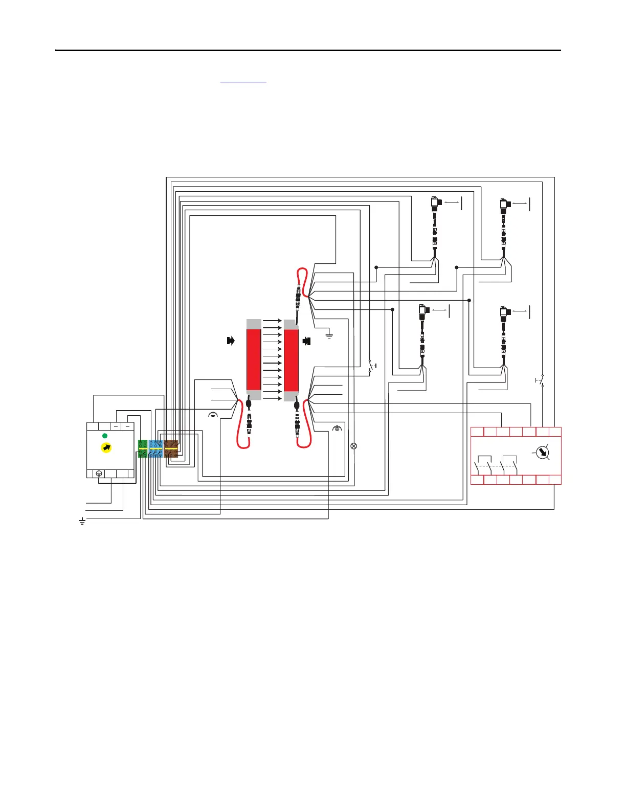
Four-sensor Muting
Schematic Example
Figure 112 shows an example wiring diagram for four-sensor muting. The muting
sensors are connected to the cascading plug-in. If the Connected Components
Workbench software is not used, the connections of the muting sensors must be
as shown in the schematic. If the Connected Components Workbench software
is used, the muting sensors can be connected in any of the muting wires and then
configured in the Connected Components Workbench software.
Figure 112 - Example Schematic for Four Sensor Muting
450L-E4FN1200YD
450L-E4FN1200YD
S11 S12 S21 S22
S34
A1
13 L11
A2
14 23 24 Y32
SI
440R-S12R2
RESET
0
MM
AM
FE
FE
Muting Sensor 2
42EF-P2MPB-F4
889D-F4AC-5 889D-F4AC-5
Muting Sensor 1
42EF-P2MPB-F4
Blue Blue
White (Not Used)
Brown
2 Brown
Black Black
Brown
450L-APT-PW-5
898D-F5NC-5
450L-APR-MU-8
898D-F8NB-5
450L-APC-IO-8
898D-F8NB-5
Tx
Rx
5 Grey OSSD1
1 White Aux.
6 Pink OSSD2
4 Yellow EDM
Mute
Dependent
Override
Mute
Active
8 Red
3 Green
7 Blue
White (Not Used)
Muting Sensor 3
42EF-P2MPB-F4
889D-F4AC-5 889D-F4AC-5
Muting Sensor 4
42EF-P2MPB-F4
Blue Blue
White (Not Used)
Brown
Black Black
Brown
White (Not Used)
Grey
Blue
Black (Not Used)
White (Not Used)
Brown
2 Brown
5 Grey MS1
1 White MS3
6 Pink MS2
4 Yellow MS4
8 Red Mute Lamp
3 Green
7 Blue
+24V DC
24V Com (0V)
L
L
++
N
N
1606-XLP95E
24-
28V
DC ok
120-240V AC
PE
Primary Protective Earth Ground
RESET
 Loading...