Rockwell Automation Publication 450L-UM001D-EN-P - December 2019 155
Connected Components Workbench Software Chapter 9
GPIO Selection and Settings
With the muting settings established, the General Purpose Input and Output
(GPIO) must be set. Click the GPIO tab.
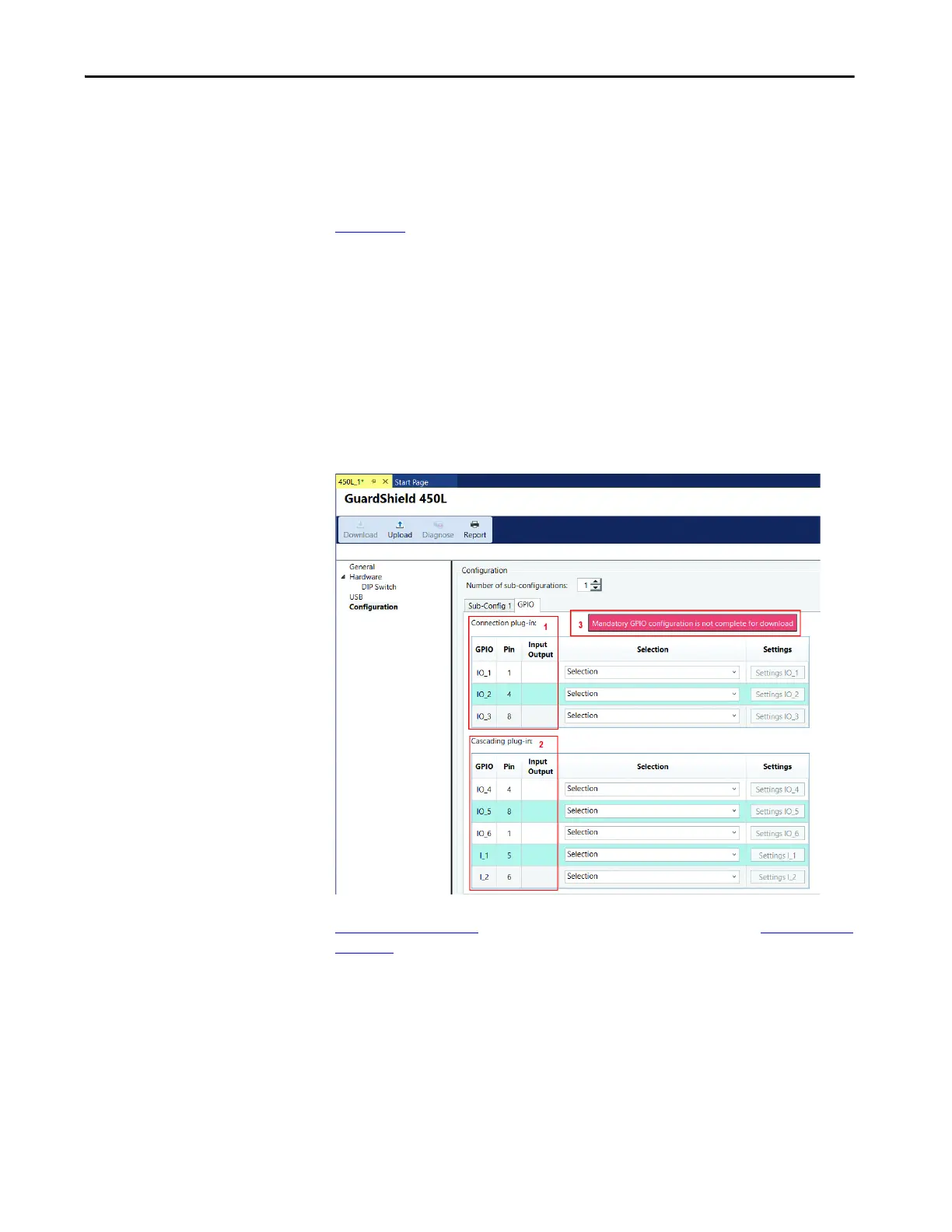
Figure 116
highlights three sections of the GPIO settings:
1. The connection plug-in has three wiring connections that can be used as
input or output. The I/O are available on connector pins 1, 4, and 8.
2. The cascading plug-in has five wiring connections. Three can be used as
input or output, and two can only be used as inputs. The I/O are available
on connector pins 4, 8, 1, 5, and 6.
3. Initially, a red message box “Mandatory GPIO configuration is not
complete for download” appears. After making the proper mandatory
selections, the message turns green.
Figure 116 - GPIO Overview
Figure 60 on page 156 lists the I/O from the example schematic in Figure 112 on
page 152. There are five inputs on the cascading plug-in and one output on the
connection plug-in.
 Loading...