156 Rockwell Automation Publication 450L-UM001D-EN-P - December 2019
Chapter 9 Connected Components Workbench Software
Table 60 - Muting I/O
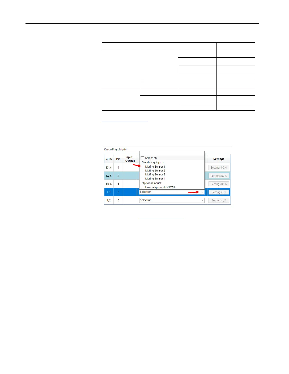
Figure 117 on page 156 shows the settings. Click the selection expander for
Cascading plug-in pin five. The four muting sensors appear as mandatory inputs.
Check Muting Sensor 1, as this sensor is connected to pin 5.
Figure 117 - Select I/O for Pin 5
Click Settings I_1. Figure 118 on page 157 shows the sensor settings to adjust the
sensor logic and filter times.
The Logic function for muting sensor is fixed at LOW Active. When an object
passes in front of the sensor, the sensor output turns OFF.
Adjust the filter times to help prevent inadvertent changes from the sensor
output from disrupting the muting process. The filter times can be adjusted from
0…255 ms.
Click OK after adjustments are made.
Plug-in I/O Function Pin
Cascading Input Muting sensor 1 5
Muting sensor 2 6
Muting sensor 3 1
Muting sensor 4 4
Output Muting lamp 8
Connection Input Muting override 8
Output Mute timing error 1
Mute sequence error 4
 Loading...