Rockwell Automation Publication 450L-UM001D-EN-P - December 2019 57
Safety Function Chapter 4
Figure 27 - Response Time Calculation for each Cascaded Pair
Connected Components Workbench Response Time
Connected Components Workbench software calculates the response time when
the configuration is locked. Figure 28
shows an example of the response time
calculated by Connected Components Workbench software. On the Diagnose
screen, scroll down the diagnostic parameter to 3.30.
Figure 28 - Response Time in Connected Components Workbench Diagnostic Parameter 3.30
Product Labels
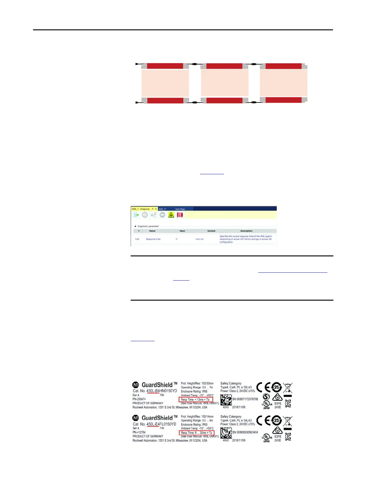
Figure 29 shows examples of the response time printed on the GuardShield sticks.
This response time should not be used to calculate the safety distance calculation.
Use the information in this user manual to determine the response time. This
information will be removed in future changes of the label.
Figure 29 - Response Time on the Product Label
IMPORTANT Determine Stop Time: The stopping time calculation must include the response
times of all devices in the stop circuit (see Determine the Safety Distance on
page 68). Not including all device and control system elements when
calculating the stopping time results in an inaccurate safety distance
calculation.
Pair 1 Pair 2
Pair 3
450L-E4FL0600YD 450L-E4FL0300YD
450L-E4FL1800YD
Tx = 12 ms
Tc = 0 ms
Tr (1) = 12+0 ms = 12 ms
Ts = 10 ms
Tc = 1 x 6 ms
Tr (2) = 10+6 ms = 16 ms
Ts = 19 ms
Tc = 2 x 6 ms
Tr (3) = 19+12 ms = 31 ms
450L-APC-IO-8
450L-APC-IO-8
 Loading...