148 Rockwell Automation Publication 450L-UM001D-EN-P - December 2019
Chapter 9 Connected Components Workbench Software
Two-sensor Muting
Schematic Example
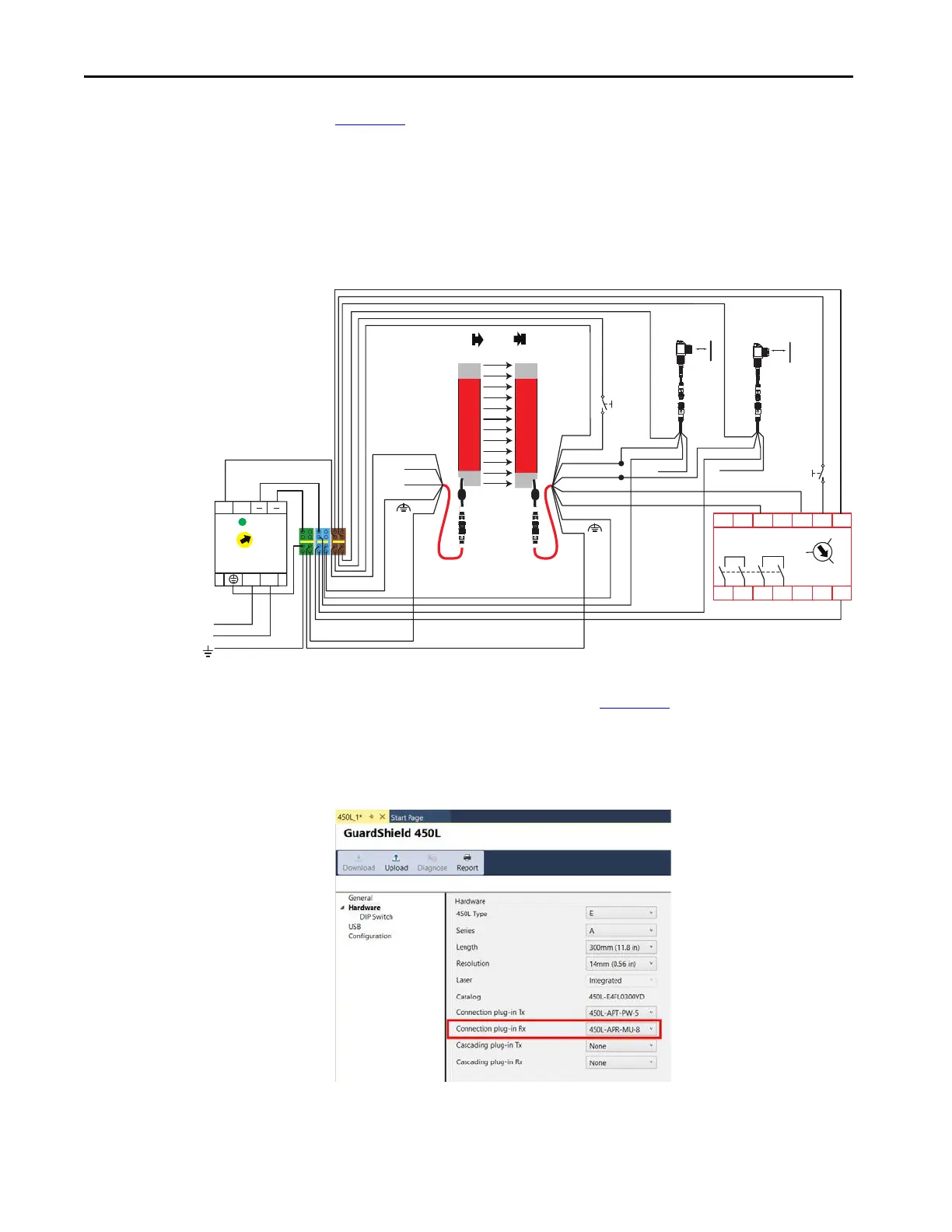
Figure 106 shows an example wiring diagram for two-sensor muting. The muting
sensors are connected to pins 1 and 4 of the connection plug-in. If the Connected
Components Workbench software is not used, the connections of the muting
sensors must be as shown in the schematic. If the Connected Components
Workbench software is used, the muting sensors can be connected in any of the
muting wires and then configured in the Connected Components Workbench
software.
Figure 106 - Example Schematic for Two Sensor Muting
In the hardware setup, which is shown in Figure 107, select the muting plug-in,
Bulletin 450L-APR-MU-8, as the Connection plug-in Rx. On the plug-in, set
switch 1 to ON, and all other switches are OFF. This step allows the Connected
Components Workbench software to configure the muting setup.
Figure 107 - Hardware Setup
450L-E4FN1200YD
450L-E4FN1200YD
S11 S12 S21 S22
S34
A1
13 L11
A2
14 23 24 Y32
SI
440R-S12R2
RESET
0
MM
AM
Muting Sensor 1
42EF-P2MPB-F4
889D-
F4AC-5
889D-
F4AC-5
Muting Sensor 2
42EF-P2MPB-F4
Blue Blue
White (Not Used)
Brown
2 Brown
Black Black
Brown
450L-APT-PW-5
898D-F5NC-5
450L-APR-MU-8
898D-F8NB-5
Tx
Rx
5 Grey OSSD1
1 White
6 Pink OSSD2
4 Yellow
Mute
Dependent
Override
8 Red
3 Green
7 Blue
White (Not Used)
5. Grey
FE
FE
3. Blue
4. Black (Not Used)
2. White (Not Used)
1. Brown
+24V DC
24V Com (0V)
L
L
++
N
N
1606-XLP95E
24-
28V
DC ok
120-240V AC
RESET
PE
Primary Protective Earth Ground
 Loading...