Rockwell Automation Publication 450L-UM001D-EN-P - December 2019 91
Installation and Wiring Chapter 6
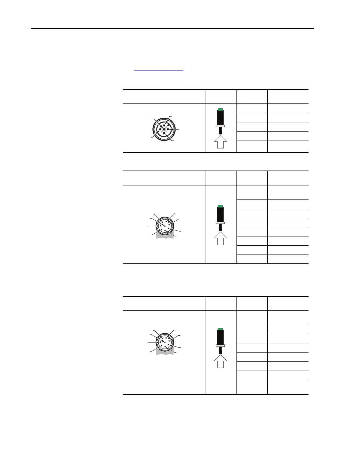
Receiver Plug-in
Any receiver plug-in type works with any transmitter plug-in type and vice versa
(see Figure 61 on page 90
).
Table 34 - Pin Assignment — Cat. Nos. 450L-APR-ON-5 and 450L-APR-BL-5
Table 35 - Pin Assignment — Cat. No. 450L-APR-ED-8
Table 36 - Pin Assignment — Cat. No. 450L-APR-MU-8 (Configured for (a) No Muting, or for (b)
Muting Sensors Connected at Cascading 450L-APC-IO-8 Plug-in)
Receiver Bottom Plug-in Face View of Male
M12 5-pin (DC Micro) View Pin Number Signal Receiver
1+24V DC
2 OSSD1
3 0V (GND)
4 OSSD2
5 Functional earth FE
Receiver Bottom Plug-in Face View of Male
M12 8-pin (DC Micro) View Pin Number Signal Receiver
1
Auxiliary output (OSSD
emulation)
2+24V DC
3 Functional earth FE
4EDM (Input)
(1)
(1) If set with DIP switches.
5 OSSD1
6 OSSD2
7 0V (GND)
8Start
(1)
Receiver Bottom Plug-in Face View of Male
M12 8-pin (DC Micro) View Pin Number Signal Receiver
1
Auxiliary output (OSSD
emulation)
2+24V DC
3 Functional earth FE
4EDM (Input)
(1)
(1) If set with DIP switches.
5 OSSD1
6 OSSD2
7 0V (GND)
8
Start
(1)
/mute
dependent override
5
4
3
1
2
 Loading...