92 Rockwell Automation Publication 450L-UM001D-EN-P - December 2019
Chapter 6 Installation and Wiring
See Table 3 7 for a configuration for muting sensors that are connected at the
450L-APR-MU-8 connection plug-in.
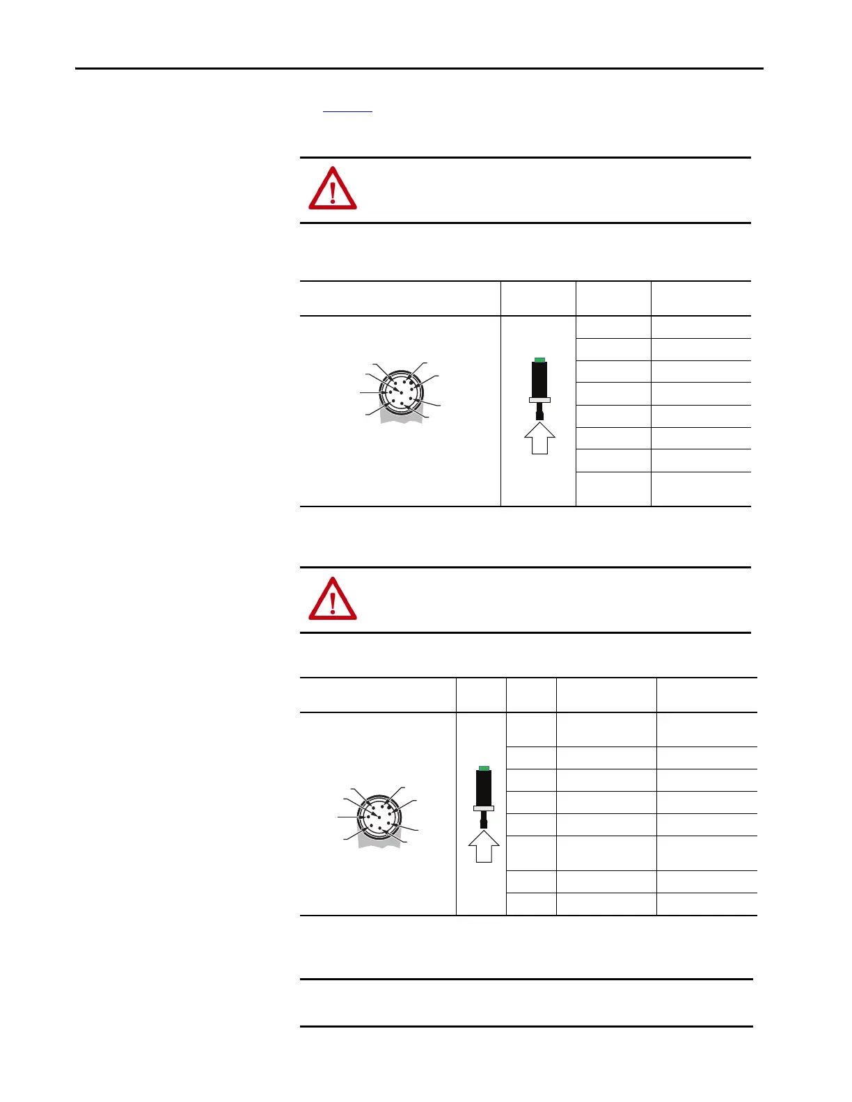
Table 37 - Pin Assignment — Cat. No. 450L-APR-MU-8 if Two-sensor Muting Are Connected at the
Connection Plug-in Are Configured (450L-E Only)
Table 38 - Pin Assignment — Cat. No. 450L-APU-UN-8
ATTENTION: The Auxiliary output is only a status output for diagnosis
purposes to connect, for example, an indicator lamp. Do not use this output
for safety purposes.
Receiver Bottom Plug-in Face View of Male
M12 8-pin (DC Micro) View Pin Number Signal Receiver
1Sensor 1
2+24V DC
3 Functional earth FE
4Sensor 2
5 OSSD1
6 OSSD2
7 0V (GND)
8
Start
(1)
/mute
dependent override
(1) If set with DIP switches.
ATTENTION: The Auxiliary output is only a status output for diagnosis
purposes to connect, for example, an indicator lamp. Do not connect this
output to fulfill safety functions.
Receiver Bottom Plug-in Face
View of Male M12 8-pin (DC Micro) View
Pin
Number Signal Transmitter Signal Receiver
1 Do not connect
Auxiliary output (OSSD
emulation)
2 +24V DC +24V DC
3 Functional earth FE Functional earth FE
4
(1)
(1) Pin 4 connected to pin 8 (short circuit).
EDM (Input)
(2)
(2) If set with DIP switches.
5 Do not connect OSSD1
6
Auxiliary output
(Lockout)
OSSD2
7 0V (GND) 0V (GND)
8
(1) (2)
IMPORTANT If pin four is connected to pin eight, the corresponding 450L safety light
curtain stick acts like a transmitter.
5
6
7
8
4
3
1
2
 Loading...