140 Rockwell Automation Publication 450L-UM001D-EN-P - December 2019
Chapter 9 Connected Components Workbench Software
GPIO
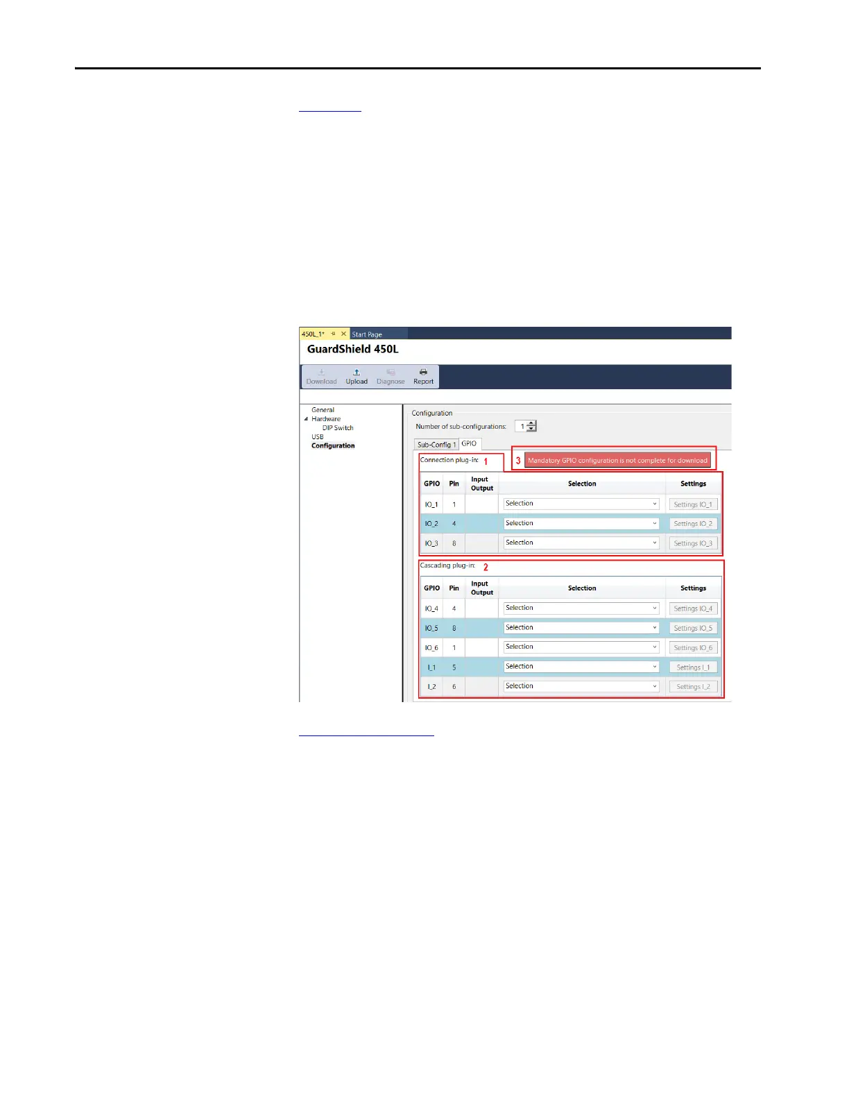
Figure 100 shows an overview of the layout of the General Purpose Input Output
(GPIO) window. The window has three significant areas:
1. Connection plug-in
2. Cascading plug-in
3. Message box — informs you whether the mandatory GPIO has been
specified
The configuration cannot be downloaded to the stick until the mandatory GPIO
is completed. When completed, the message box has a green background.
Figure 100 - GPIO Overview
Figure 101 on page 141 shows an example of the General Purpose Input Output
selections. The Connected Components Workbench software automatically
determines the available pins on the connection [1] and cascading [2] plug-ins. A
message [3] is displayed to show whether mandatory configuration points are
selected. When complete, the message background turns from red to green.
The subconfiguration setup automatically determines the available selections.
This selection is a four-sensor muting example with two subconfigurations. The
connection plug-in has three I/O and the cascading plug-in has three I/O (inputs
or outputs) and two I (inputs).
 Loading...