60 Rockwell Automation Publication 450L-UM001D-EN-P - December 2019
Chapter 5 System Configuration
The universal plug-in can be set to perform as an emitter or receiver. If pins four
and eight of the connectors are short circuited at power-up, the stick behaves like
a transmitter. In this case, the DIP switches have no functionality. Also the beam
coding functionality is still set at the 450L-E Receiver (Rx). For the confirmation
of the beam coding configuration and the pairing procedure, see Confirmation of
a New System Configuration on page 64. If pin four and pin eight of the plug-in
are not short circuited at power-up, the corresponding stick behaves like a
receiver. In this case, the DIP switches have the same functionality as the
450L-APR-ED-8 receiver plug-in.
Receiver Plug-in DIP Switch
Settings
The transmitter plug-ins and the cascading plug-ins don’t have DIP switches.
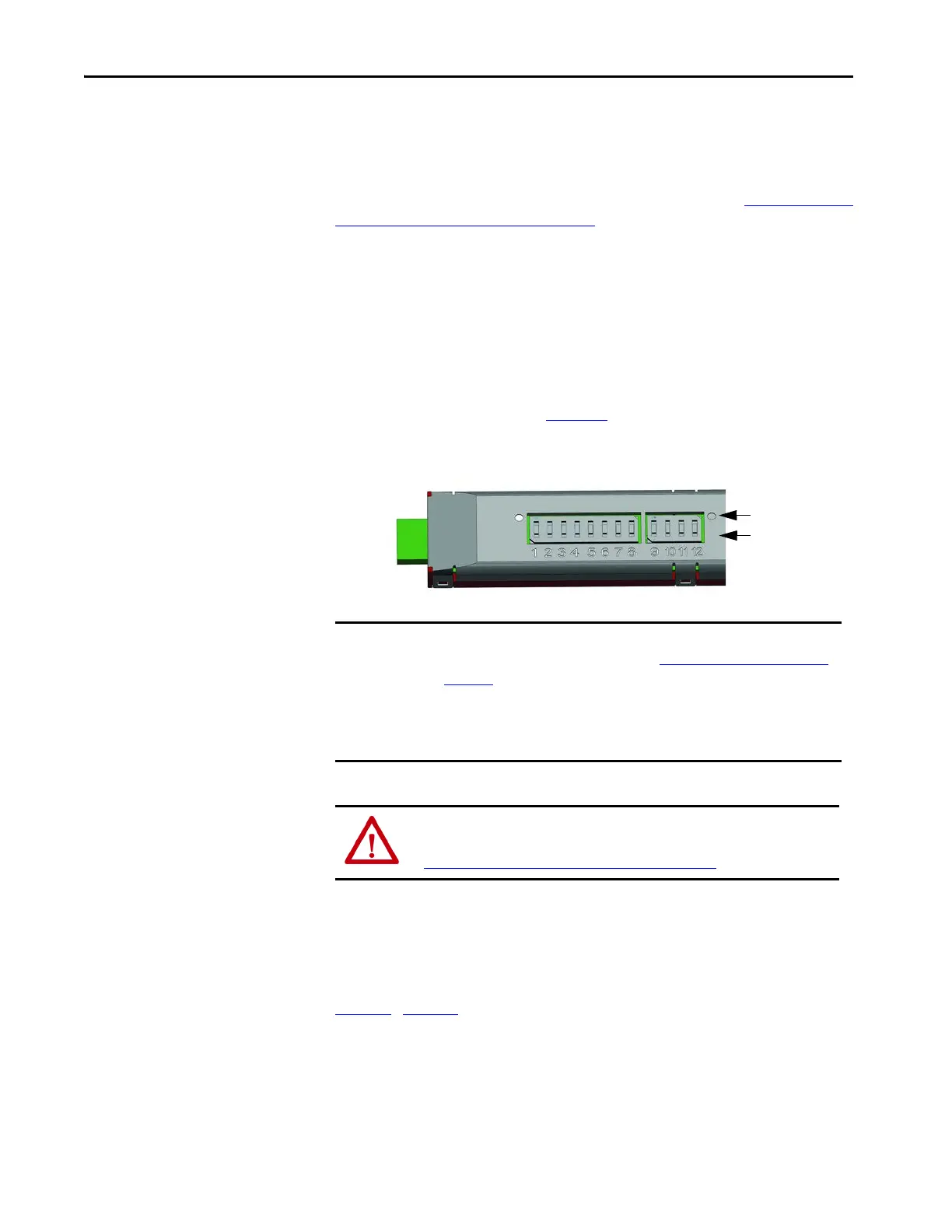
Identify and set the appropriate DIP switches for the configuration desired. DIP
switch identification is shown in Figure 30
. The number of DIP switches varies
depending on the plug-in type.
Figure 30 - DIP Switch Location at Receiver Plug-in
After installing the plug-in on the 450L-B transmitter stick and power-up, a
configuration confirmation can be performed (signaled by the red/ green
blinking of the STS status indicator). The confirmation of the configuration can
be performed without receiver and transmitter aligned.
Tabl e 21
…Ta ble 2 7 describe the switch functions and default settings for the
receiver plug-ins.
IMPORTANT DIP switches must be switched to OFF if the Switch Function is not defined.
Otherwise, an error condition occurs (see Status Indicator Error Display on
page 116).
After each reconfiguration of a safety light curtain, test the system for proper
configuration and operation before placing the guarded machine in
operation.
ATTENTION: Every modification of the DIP switches must be confirmed with
a configuration confirmation procedure after the first power-up (see
Confirmation of a New System Configuration on page 64
).
 Loading...