Rockwell Automation Publication 450L-UM001D-EN-P - December 2019 97
Installation and Wiring Chapter 6
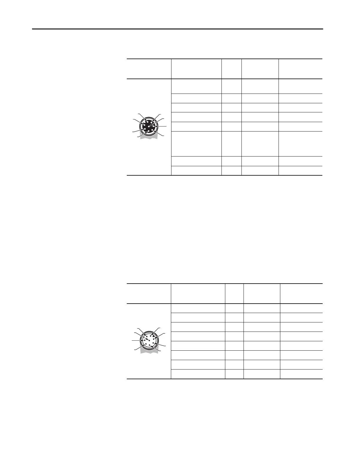
Table 47 - Pin Assignment of the Cable if Connected to a M12 Eight-pin Universal Plug-in;
(Depending on Wiring Can Either Be a Transmitter or a Receiver) (Cat. No. 450L-APU-UN-8)
Cascading Cable Connection
The pin assignment for the cable connected to a cascading plug-in (catalog
number 450L-APC-IO-8) depends on if the cascading plug-in is inserted in a
450L-E transceiver stick working as a transmitter or as a receiver. It also depends
on the settings of the DIP switches on the RX plug-in.
Table 48 - Pin Assignment of the Cable if Connected to a M12 8-pin I/O Cascading Plug-in; (Cat. No.
450L-APC-IO-8)
Connection Cable
Face View of Female
M12 8-pin (DC Micro)
Color
(Cat. No. 889D-F8AB-x)
(1)
(1) Replace x with 2, 5, 10, 15, 20, or 30 for available lengths in meters.
Pin
Number
Signal
Transmitter Signal Receiver
White 1 —
Auxiliary output (OSSD
high = 24V)
Brown 2 +24V DC +24V DC
Green 3 Functional earth FE Functional earth FE
Yel lo w 4
(2)
(2) Pin 4 connected to pin 8 (short circuit).
EDM (Input)
(3)
(3) If set with DIP switches.
Gray 5 Do not connect OSSD1
Pink 6
Auxiliary output
(Lockout) (24V =
normal operation,
0V = lockout)
OSSD2
Blue 7 0V (GND) 0V (GND)
Red 8
(2) (3)
Connection Cable
Face View of Male
M12 8-pin (DC Micro)
Color
(Cat. No. 889D-M8AB-x)
(1)
(1) Replace the x with 2 [2 m (6.6 ft)], 5 [5 m (16.4 ft)], 10 (10 m (32.8 ft)] for desired length.
Pin No.
Signal
Transmitter
Signal Receiver
(4 Sensor Muting)
(2)
(2) If set with DIP switches.
White 1 — Muting sensor S3 in
Brown 2 +24V DC +24V DC
Green 3 Functional earth FE Functional earth FE
Yellow 4 — Muting sensor S4 in
Gray 5 — Muting sensor S1 in
Pink 6 — Muting sensor S2 in
Blue 7 0V (GND) 0V (GND)
Red 8 — Muting lamp
5
6
7
8
4
3
1
2
 Loading...