76 Rockwell Automation Publication 450L-UM001D-EN-P - December 2019
Chapter 6 Installation and Wiring
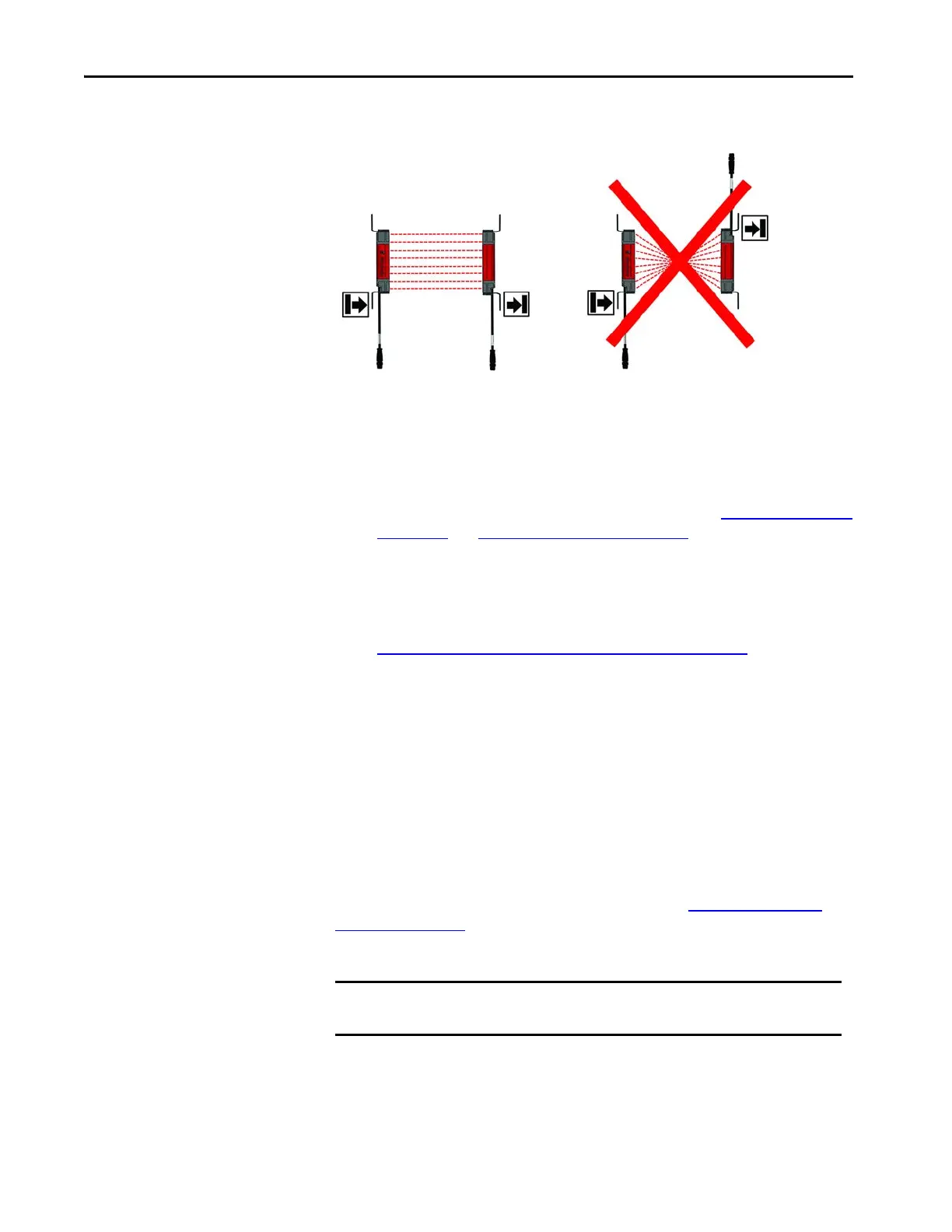
Figure 40 - Correct Positioning and Incorrect Positioning of Transmitter and Receiver Sticks
• The optical lens system of transmitter and receiver stick must be in exact
opposition to each other.
• Take suitable measures to attenuate vibration.
• The safety light curtain must be mounted such that the hazardous point
cannot be reached from below, above, or behind the safety light curtain
and that the light curtain cannot be repositioned (see Correct Installation
on page 77 and Incorrect Installation on page 78).
•Connect both sticks.
• Turn on power to the GuardShield safety light curtain system.
• If the STS status indicator at the receiver stick displays a configuration
change (blinking red/green), confirmation is required to proceed with
Confirmation of a New System Configuration on page 64
.
• Rotate the transmitter and receiver sticks while watching the two status
indicators on the sticks. Find the point where the two indicators for the
intensity state illuminate to a solid green condition.
• Determine the maximum left and right adjustment angles and position
each unit in the center. Tighten all hardware until the alignment
(intensity) indicators are not blinking.
• Cycle power to confirm that the system powers up, goes to the ON state
(STS status indicator solid green) and the intensity status indicators
indicate solid green.
An external laser alignment tool (440L-ALAT) and a dedicated mounting
bracket (450L-ALAT-C) are offered as accessories (see Alignment Tool and
Bracket on page 202). Use these items for aligning the 450L-B safety light curtain
for larger operating distances or when corner mirrors are used in the application.
IMPORTANT If EDM or manual start functions are configured through DIP switch settings,
confirm that the proper receiver wire connections are made.
 Loading...