Rockwell Automation Publication 450L-UM001D-EN-P - December 2019 95
Installation and Wiring Chapter 6
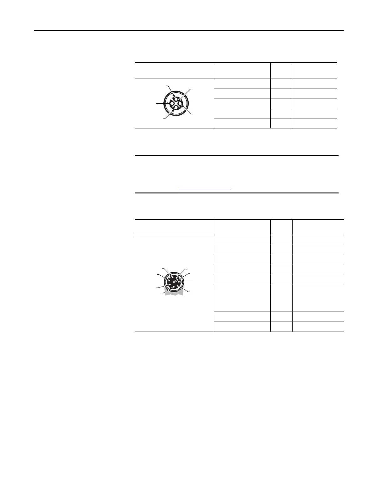
Table 43 - Pin Assignment of the Cable if Connected to a M12 5-pin Transmitter Bottom Plug-in
(Cat. No. 450L-APT-PW-5)
Table 44 - Pin Assignment of the Cable if Connected to a M12 8-pin Transmitter Bottom Plug-in
(Cat. No. 450L-APT-PW-8)
Transmitter Connection Cable Face
View of Female M12 5-pin (DC Micro)
Color
(Cat. No. 889D-F5BC-x)
(1)
(1) Replace x with 2, 5, 10, 15, 20, or 30 for available lengths in meters.
Pin
Number Signal Transmitter
Brown 1 +24V DC
White 2 Not connected
Blue 3 0 (GND)
Black 4 Not connected
Gray 5 Functional earth FE
IMPORTANT The transmitter itself is not expected to be connected to the ArmorBlock
Guard I/O module or a GuardLink tab. Consider a separate connection cable
or use the 5-pin T-connector for implementation of a transmitter (see
T-connector on page 104
).
Transmitter Connection Cable Face
View of Female M12 8-pin (DC Micro)
Color
(Cat. No. 889D-F8AB-x)
(1)
(1) Replace x with 2, 5, 10, 15, 20, or 30 for available lengths in meters.
Pin
Number Signal Transmitter
White 1 Do not connect
Brown 2 +24V DC
Green 3 Functional earth FE
Yellow 4 Do not connect
Gray 5 Do not connect
Pink 6
Auxiliary output (lockout
stick) (24V = normal
operation, 0V = lockout
stick)
Blue 7 0V (GND)
Red 8 Do not connect
 Loading...