Frame 3A and 3B Installation 3-31
PowerFlex® 700L Liquid-Cooled Drive User Manual
Publication 20L-UM001D-EN-P
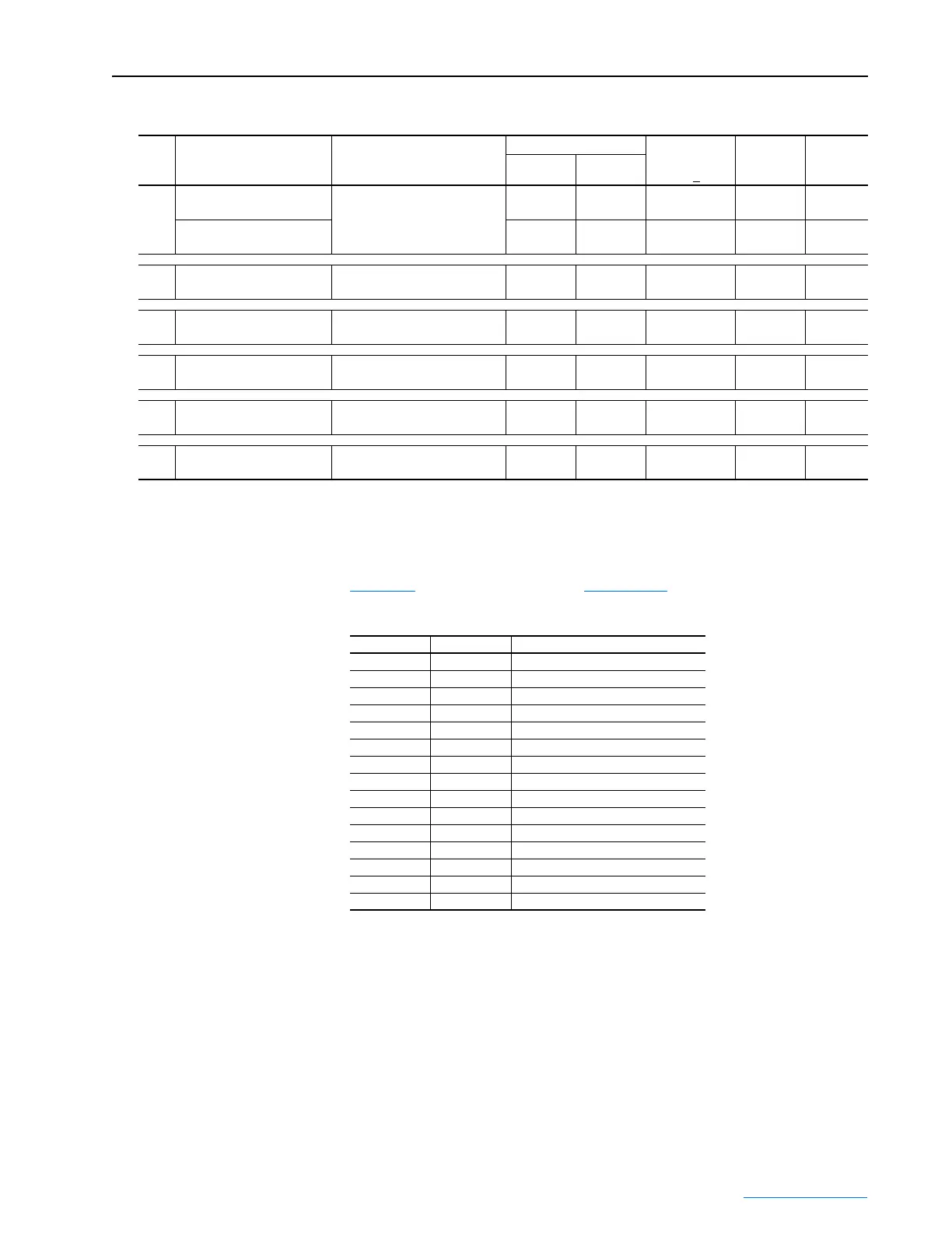
Table 3.D Power Module Control Wiring Terminal Specifications
Wire the Input Filter Bay to the Power Module Bay in accordance with
Table 3.E
and drive schematics in Appendix C.
Table 3.E Input Filter-to-Power Module Bay Wiring
Item Name Description
Wire Size Range
(1)
Recommended
Tightening
Torque (+10%)
Wire Strip
Length
Wire
Terminal
Maximum Minimum
➊
400/480V Line Voltage Fuses
FU7, FU8, and FU9
Input filter AC power 21.1 mm
2
(#4 AWG)
2.1 mm
2
(#14 AWG)
4 N•m
(35 lb•in)
(2) (2)
600/690V Line Voltage Fuses
FU7, FU8, and FU9
21.1 mm
2
(#4 AWG)
2.1 mm
2
(#14 AWG)
4 N•m
(35 lb•in)
6 mm
(0.25 in.)
not
applicable
➋
Terminal Blocks—TB2 Input filter control signals 3.3 mm
2
(#12 AWG)
0.3 mm
2
(#22 AWG)
1.5 N•m
(13 lb•in)
13 mm
(0.51 in.)
not
applicable
➌
Active Converter Cassette
Terminal Blocks—P1 & P2
Active Converter AC power and
control wiring
3.3 mm
2
(#12 AWG)
0.3 mm
2
(#22 AWG)
0.8 N•m
(7 lb•in)
8 mm
(0.31 in.)
not
applicable
➍
SHLD Terminal Terminating point for control
wiring shields on Power Module
2.1 mm
2
(#14 AWG)
0.3 mm
2
(#22 AWG)
1.4 N•m
(12 lb•in)
10 mm
(0.39 in.)
not
applicable
➎
Terminal Blocks—TB5 and
TB6
Power Module control wiring 4.0 mm
2
(#10 AWG)
0.2 mm
2
(#24 AWG)
1.4 N•m
(12 lb•in)
8 mm
(0.31 in.)
not
applicable
➏
Fan—M6 Power Module Bay cooling fan 4.0 mm
2
(#10 AWG)
0.3 mm
2
(#22 AWG)
0.8 N•m
(7 lb•in)
8 mm
(0.31 in.)
not
applicable
(1)
Maximum/minimum sizes that the terminals will accept - these are not recommendations.
(2)
For 400/480V applications, terminate wires with #10 spade tongue terminal. Maximum terminal width is 11 mm (0.43 in.). Wire strip length per terminal
manufacture’s recommendation.
From To Comments
FU7 PMC P2-1 PMC = Power Module, Converter
FU8 PMC P2-4
FU9 PMC P2-7
TB2-1 PMC P1-9
TB2-1 PMC TB5-1
TB2-3 M6-N M6 = Power Module Bay Door Fan
TB2-4 PMC TB5-3
TB2-5 PMC P1-10
TB2-6 PMC TB5-2
TB2-6 M6-L1
TB2-7 M6-PE
TB2-9 PMC TB5-4
TB2-10 PMC TB5-7
TB2-11 PMC TB5-5
PMC TB5-4 PMC TB5-6 Factory-installed jumper
 Loading...


