Communications
14 SEL-351P Quick-Start Installation and User's Guide (Portuguese)
Serial Ports
Three EIA-232 serial communications ports are available:
• Serial Port 2 (side panel)
• Serial Port 3 (side panel)
• Serial Port F (front panel)
An EIA-485 serial communications port is available as an ordering
option:
• Serial Port 1 (side panel)
Serial Port Default Settings
The default settings for all serial ports are:
Baud Rate = 2400
Data Bits = 8
Parity = N
Stop Bits = 1
The serial port default settings can be changed from the front-panel
interface or from the serial communications port itself. After connecting
the appropriate communications cable and setting the terminal emulator,
press the ENTER key, and the control will respond with a “=” prompt,
which indicates Level 0 access is established – see
Table 4.
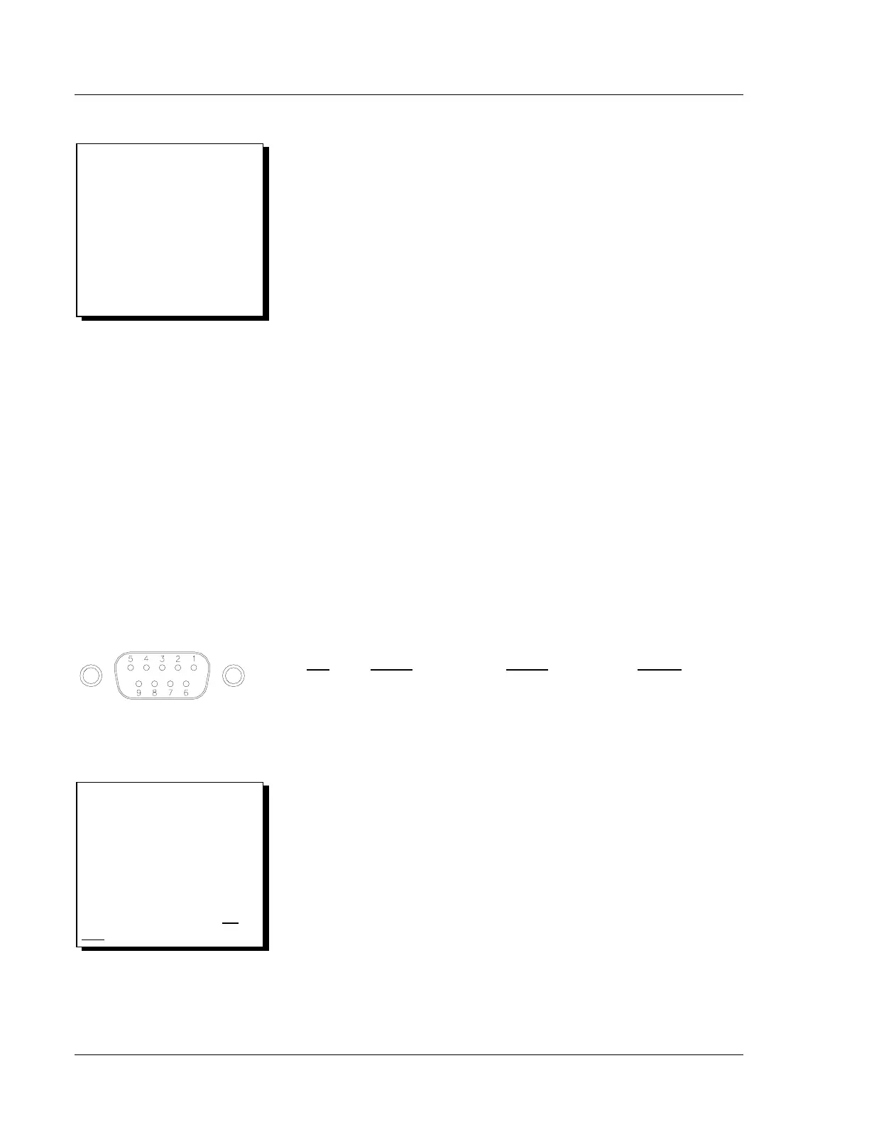
EIA-232 Pinout Functions for Ports 2, 3, and F
Pin
Port 2 Port 3 Port F
1 N/C* or +5 Vdc N/C* or +5 Vdc N/C
2 RXD RXD RXD
3 TXD TXD TXD
4 +IRIG-B N/C N/C
5, 9 GND GND GND
6 -IRIG-B N/C N/C
7 RTS RTS RTS
8 CTS CTS CTS
* Pin 1 not connected for Ports 2 and 3 when shipped from
the factory.
DWG: M351R078
DB-9 Connector Pinout (female)
for EIA-232 Serial Ports
Make Only One IRIG-B
Connection:
If making an IRIG-B connection,
connect demodulated IRIG-B time
code to either the serial Port 2 or
serial Port 1 connector (see the
following EIA-485 Pinout
Functions for Port 1), but not
both
.
Wake-Up Port:
Figure 2 shows a Wake-Up Port.
Its pin functions are defined in the
following Serial Communica-
tions Port Pin Function
Definitions. See the front of
Section 10 in the SEL-351P
Manual Técnico for more
information on the Wake-Up Port.