Date Code 990215 Inputs, Outputs, Timers, and Other Control Logic 7-15
SEL-351P Manual Técnico
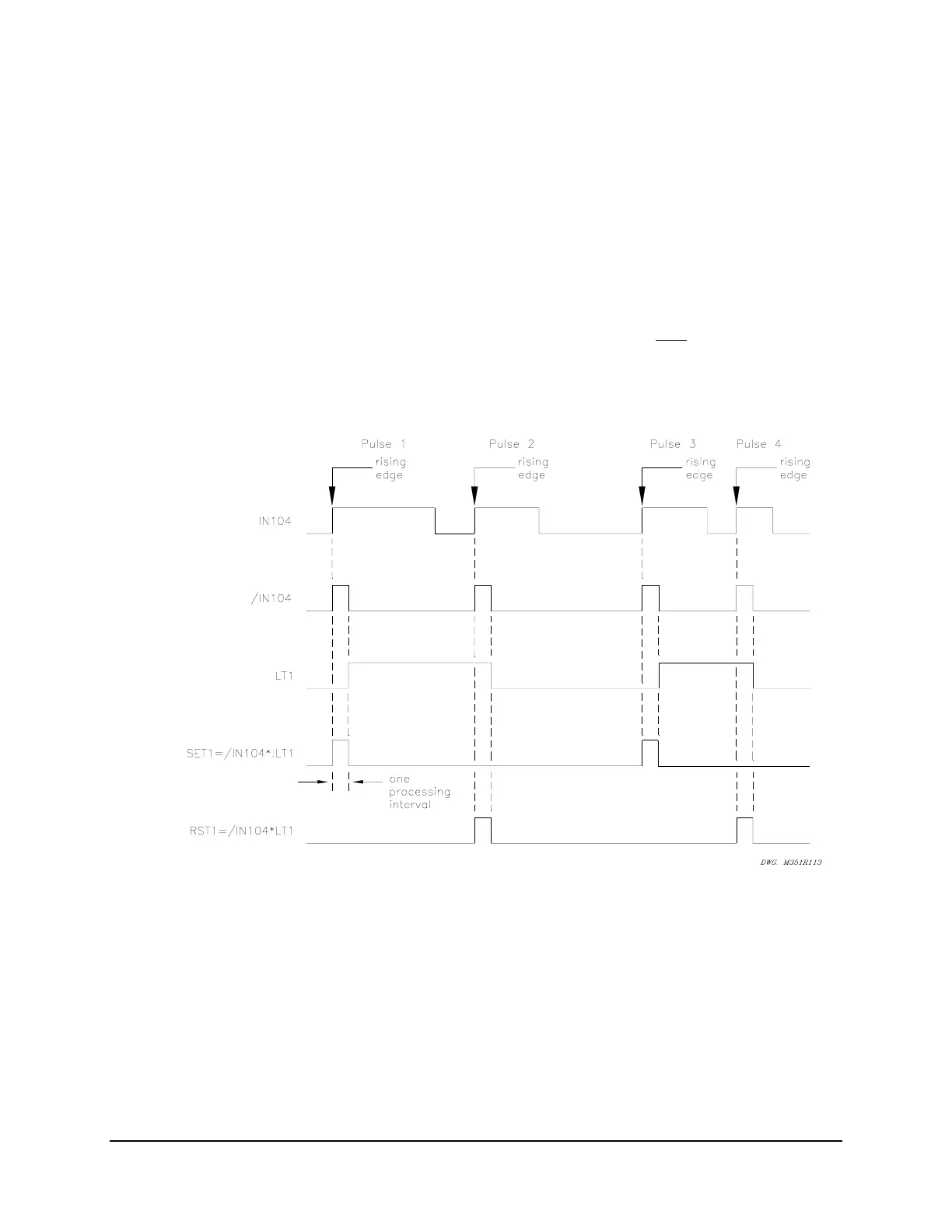
This would then appear to enable the “reset” input (setting RST1), the next processing interval.
But the “rising edge” condition occurred in the preceding processing interval, causing /IN104 to
then deassert to logical 0. So, since /IN104 is now at logical 0, setting RST1 does not assert,
even though input IN104 remains asserted for at least a few cycles by the SCADA contact.
If the SCADA contact deasserts and then asserts again (new rising edge – see Pulse 2 in
Figure SECTION 7: .14), the “reset” input (setting RST1) asserts and latch bit LT1 deasserts
back to logical 0 again. Thus, each individual assertion of input IN104 (Pulse 1, Pulse 2, Pulse 3,
and Pulse 4 in
Figure SECTION 7: .14) changes the state of latch control switch just once.
Note: Refer to preceding subsection Optoisolated Inputs and
Figure SECTION 7: .1. Relay
Word bit IN104 shows the state of optoisolated input IN104 after
the input
pickup/dropout debounce timer IN104D. Thus, when using Relay Word bit IN104 in
Figure SECTION 7: .11 and Figure SECTION 7: .12 and associated SEL
OGIC
Control
Equations, keep in mind any time delay produced by the input pickup/dropout
debounce timer IN104D.
Figure SECTION 7: .14: Latch Control Switch Operation Time Line
Use a Remote Bit Instead to Enable/Disable the Reclosing Relay
Use a remote bit to enable/disable the reclosing relay, instead of an optoisolated input. For
example, substitute remote bit RB1 for optoisolated input IN104 in the settings accompanying
Figure SECTION 7: .13: