7-12 Inputs, Outputs, Timers, and Other Control Logic Date Code 990215
SEL-351P Manual Técnico
the external contacts wired to the latching relay inputs are from remote control equipment (e.g.,
SCADA, RTU).
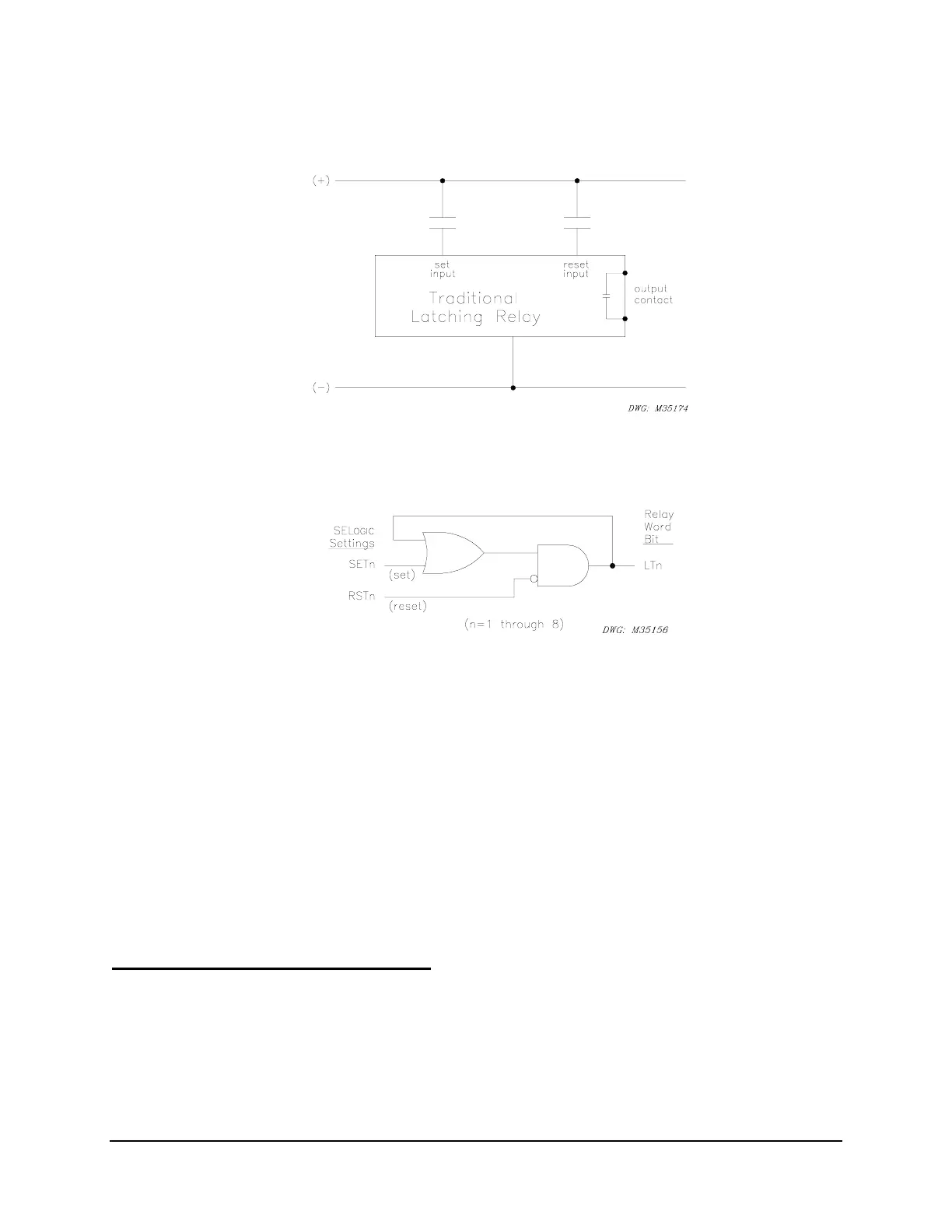
Figure SECTION 7: .10: Traditional Latching Relay
The eight latch control switches in the SEL-351P provide latching relay type functions.
Figure SECTION 7: .11: Latch Control Switches Drive Latch Bits LT1 Through LT8
The output of the latch control switch in
Figure SECTION 7: .11 is a Relay Word bit LTn (n = 1
through 8), called a latch bit. The latch control switch logic in
Figure SECTION 7: .11 repeats
for each latch bit LT1 through LT8. Use these latch bits in SEL
OGIC
Control Equations.
These latch control switches each have the following SEL
OGIC
Control Equation settings:
SETn (set latch bit LTn to logical 1)
RSTn (reset latch bit LTn to logical 0)
If setting SETn asserts to logical 1, latch bit LTn asserts to logical 1. If setting RSTn asserts to
logical 1, latch bit LTn deasserts to logical 0. If both settings SETn and RSTn assert to logical 1,
setting RSTn has priority and latch bit LTn deasserts to logical 0.
Latch Control Switch Application Ideas
Latch control switches can be used for such applications as:
• Reclosing relay enable/disable
• Ground relay enable/disable
• Sequence coordination enable/disable