1-32 Factory-Set Logic Date Code 990215
SEL-351P Manual Técnico
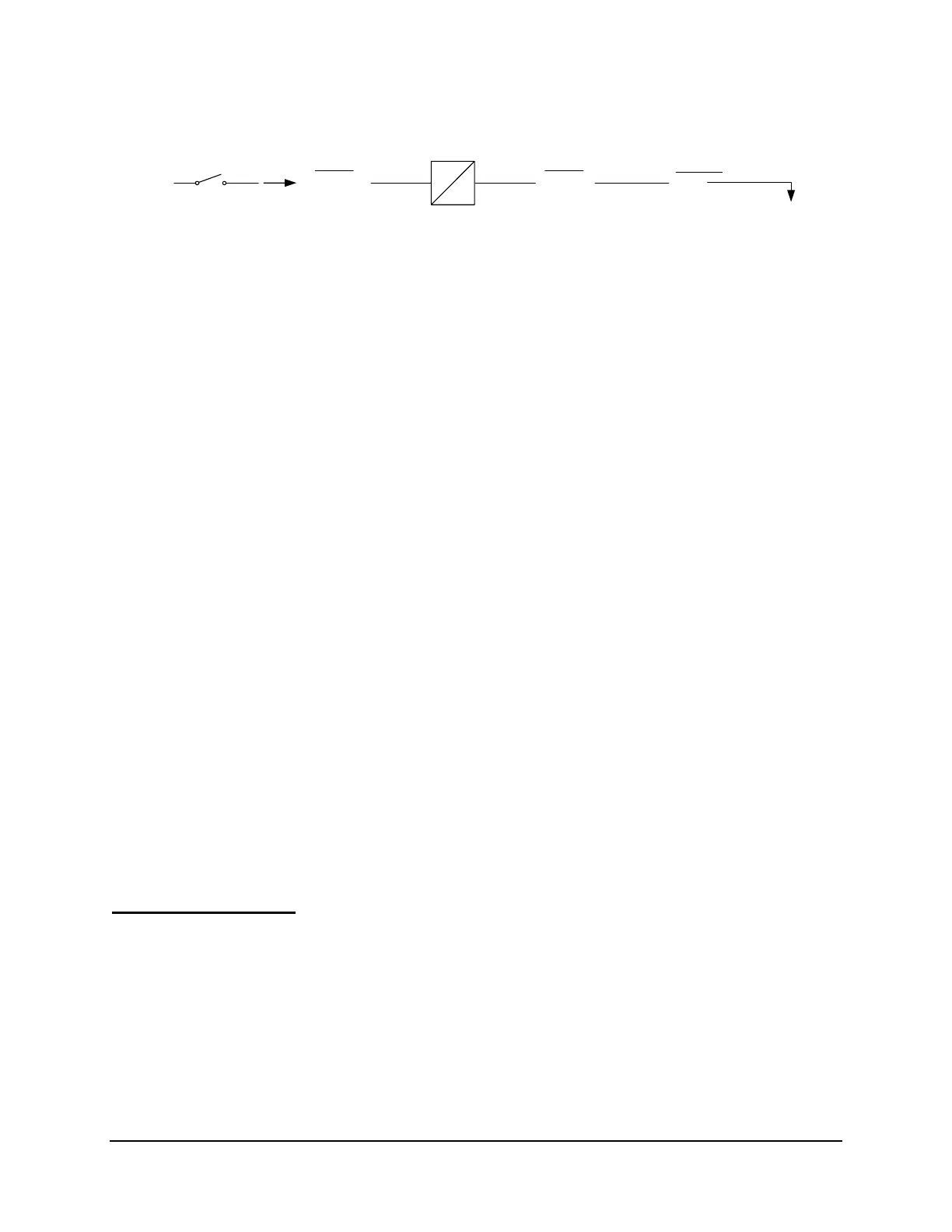
52a
DWG: M351P032
Recloser
Status
SEL
OGIC
Setting
52A
Input into
close logic
(see
Figure
6.1)
1 CYC
0.25
CYC
Relay
Word
Bit
WB52A
Relay
Word
Bit
RAW52A
Figure SECTION 1: .22: Recloser Status Determination
Figure SECTION 1: .20 through Figure SECTION 1: .22 all propagate into the close logic (see
Figure 6.1). The close signal output (Relay Word bit CLOSE) is then routed to the final
trip/close logic and subsequent output contacts (see Figure 7.29).
D
RIVE
-
TO
-L
OCKOUT
L
OGIC
SEL
OGIC
Variables SV13, SV14, SV15, and SV16 are used as intermediate steps in realizing the
entire drive-to-lockout logic (see
Figure SECTION 1: .23 through Figure SECTION 1: .25).
Other details in
Figure SECTION 1: .23:
• If setting Min. trip - ground is set below 0.1 Amp secondary, 51N1T and 51N2T operate
as Fast curve - ground and Delay curve - ground, respectively (51G1T and 51G2T are
turned off automatically). Otherwise, 51G1T and 51G2T operate as Fast curve - ground
and Delay curve - ground, respectively (51N1T and 51N2T are turned off
automatically).
• If setting High current trip - ground is set effectively below 0.05 Amp secondary,
67N2T operates as High current trip - ground (67G2T is turned off automatically).
Otherwise, 67G2T operates as High current trip - ground (67N2T is turned off
automatically).
• If setting Min. trip - ground is set below 0.1 Amp secondary, 50N6 provides the
indication that ground current is above the Min. trip - ground setting value (50G6 is
turned off automatically). Otherwise, 50G6 provides the indication (50N6 is turned off
automatically).
Operations to Lockout
The logic for the operations to lockout settings for phase, ground and SEF elements is found in
preceding
Figure SECTION 1: .8 through Figure SECTION 1: .10. The output of this logic
(Relay Word bits OLP, OLG, and OLS) is used in the drive-to-lockout logic in
Figure SECTION
1: .24 and top of
Figure SECTION 1: .25.
The SEL-351P is driven to lockout if all the following are true:
• The number of trip operations is greater than or equal to setting Operations to lockout -
ground (Relay Word bit OLG asserted to logical 1)