Date Code 990215 Inputs, Outputs, Timers, and Other Control Logic 7-13
SEL-351P Manual Técnico
Latch control switches can be applied to almost any control scheme. The following is an
example of using a latch control switch to enable/disable the reclosing relay in the SEL-351P.
Reclosing Relay Enable/Disable Setting Example
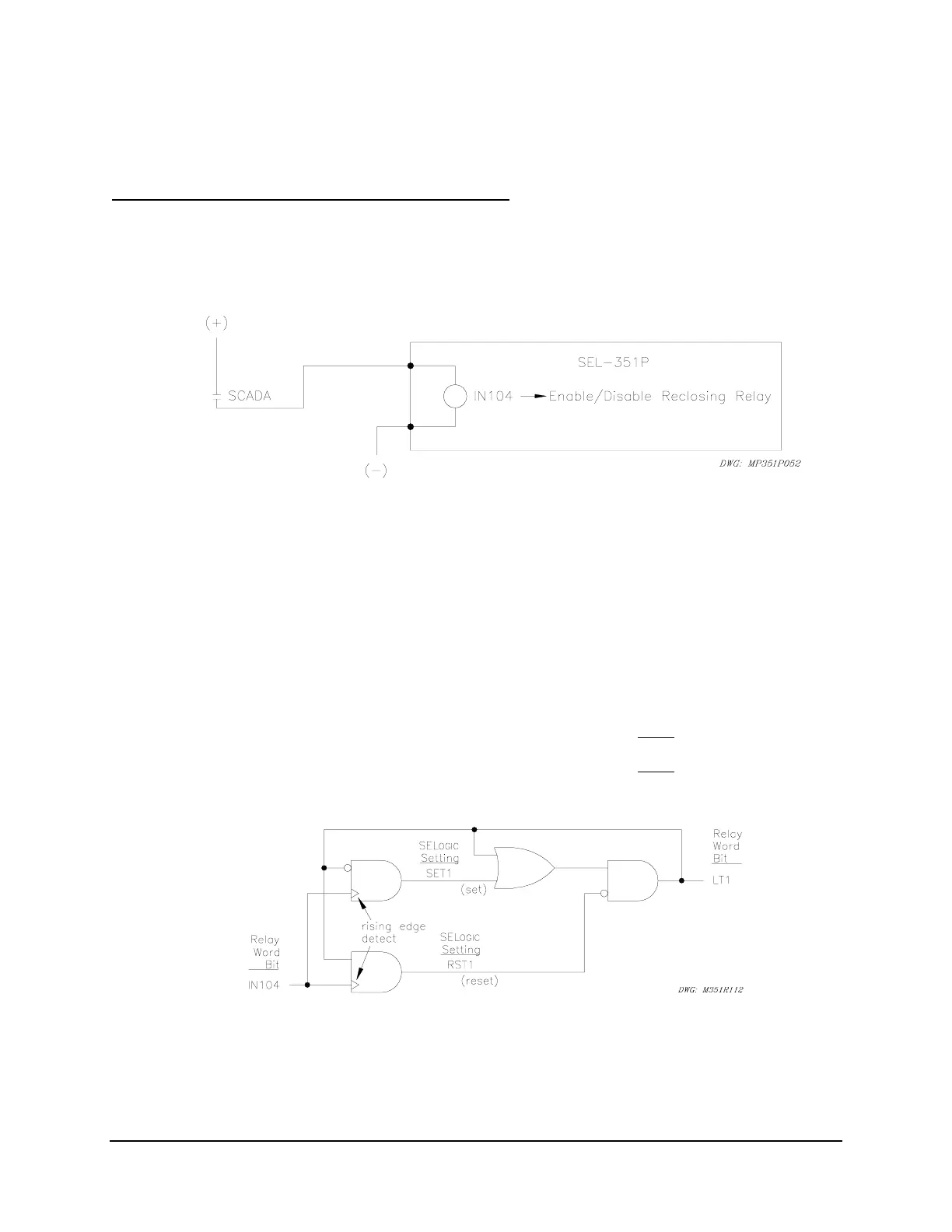
Use a latch control switch to enable/disable the reclosing relay in the SEL-351P. In this
example, a SCADA contact is connected to optoisolated input IN104. Each pulse of the SCADA
contact changes the state of the reclosing relay. The SCADA contact is not maintained, just
pulsed to enable/disable the reclosing relay.
Figure SECTION 7: .12: SCADA Contact Pulses Input IN4 to Enable/Disable
Reclosing Relay
If the reclosing relay is enabled and the SCADA contact is pulsed, the reclosing relay is then
disabled. If the SCADA contact is pulsed again, the reclosing relay is enabled again. The
control operates in a cyclic manner:
pulse to enable ... pulse to disable ... pulse to enable ... pulse to disable ...
This reclosing relay logic is implemented in the following SEL
OGIC
Control Equation settings
and displayed in
Figure SECTION 7: .13.
SET1 = /IN104 * !LT1 [= (rising edge of input IN104) AND
NOT(LT1)]
RST1 = /IN104 * LT1 [= (rising edge of input IN104) AND
LT1]
79DTL = !LT1 [= NOT(LT1); drive-to-lockout setting]
Figure SECTION 7: .13: Latch Control Switch Controlled by a Single Input to
Enable/Disable Reclosing