4-20 Loss-of-Potential, Load Encroachment, and Directional Element Logic Date Code 990430
SEL-351P Manual Técnico
D
IRECTIONAL
C
ONTROL FOR
N
EGATIVE
-S
EQUENCE AND
P
HASE
O
VERCURRENT
E
LEMENTS
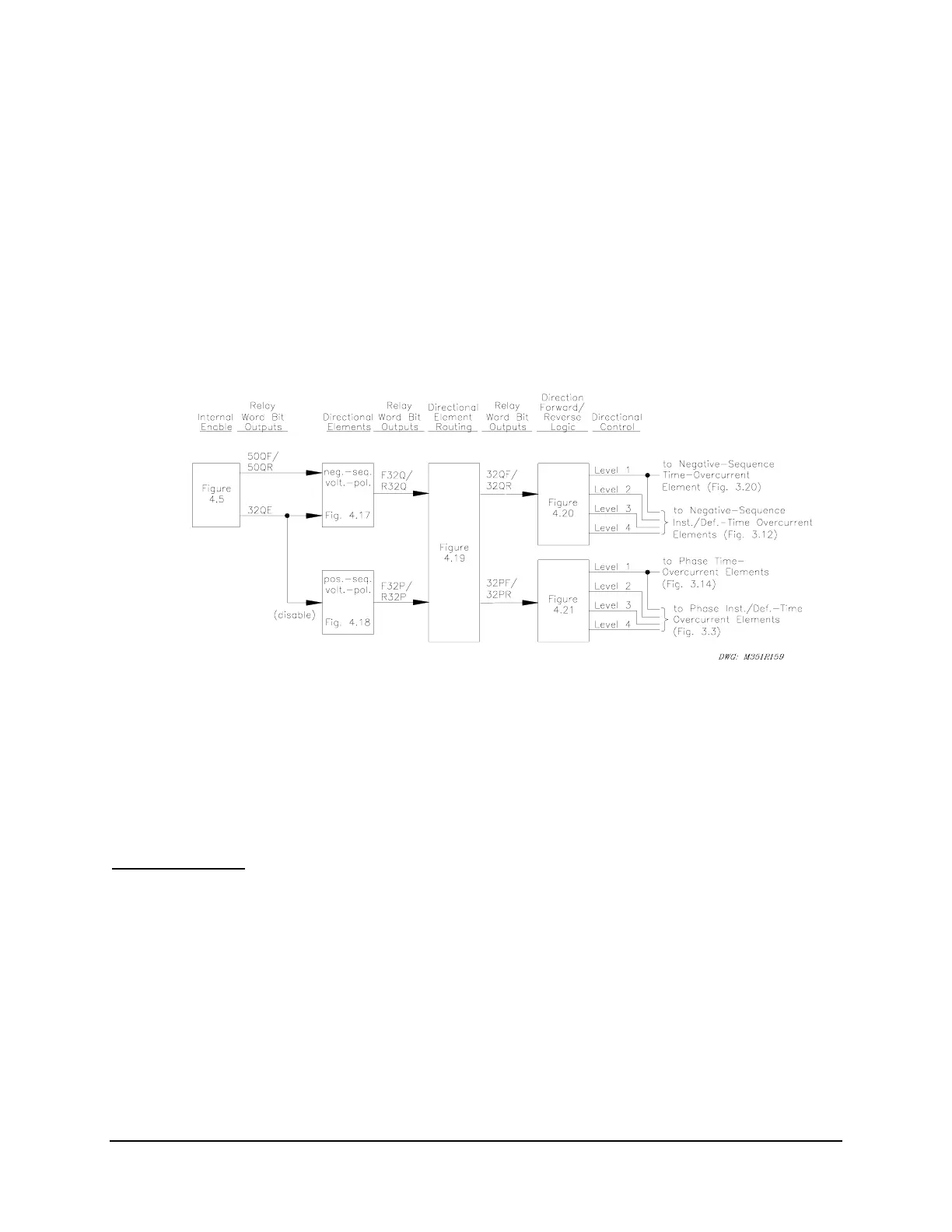
The directional control for overcurrent elements is enabled by making directional control enable
setting E32. Setting E32 and other directional control settings are described in the following
subsection Directional Control Settings.
The negative-sequence voltage-polarized directional element controls the negative-sequence
overcurrent elements. Negative-sequence voltage-polarized and positive-sequence voltage-
polarized directional elements control the phase overcurrent elements.
Figure SECTION 4: .17
gives an overview of how the negative-sequence voltage-polarized and positive-sequence
voltage-polarized directional elements are enabled and routed to control the negative-sequence
and phase overcurrent elements.
Figure SECTION 4: .16: General Logic Flow of Directional Control for Negative-
Sequence and Phase Overcurrent Elements
The negative-sequence voltage-polarized directional element has priority over the positive-
sequence voltage-polarized directional elements in controlling the phase overcurrent elements.
The negative-sequence voltage-polarized directional element operates for unbalanced faults,
while the positive-sequence voltage-polarized directional element operates for three-phase faults.
Internal Enables
Refer to
Figure SECTION 4: .5 and Figure SECTION 4: .16.
The internal enable 32QE corresponds to the negative-sequence voltage-polarized directional
element.
Note that
Figure SECTION 4: .5 has extra internal enable 32QGE, which is used in the
directional element logic that controls the neutral ground and residual ground overcurrent
elements (see
Figure SECTION 4: .4).
The settings involved with internal enable 32QE in
Figure SECTION 4: .5 (e.g., settings a2, k2)
are explained in a following subsection Directional Control Settings.