4-28 Loss-of-Potential, Load Encroachment, and Directional Element Logic Date Code 990430
SEL-351P Manual Técnico
Settings
DIR1 – Level 1 Overcurrent Element Direction Setting
DIR2 – Level 2 Overcurrent Element Direction Setting
DIR3 – Level 3 Overcurrent Element Direction Setting
DIR4 – Level 4 Overcurrent Element Direction Setting
Setting Range:
F = Direction Forward
R = Direction Reverse
N = Nondirectional
Table SECTION 4: .1 shows the overcurrent elements that are controlled by each level direction
setting. Note in
Table SECTION 4: .1 that all the time-overcurrent elements (51_T elements)
are controlled by the DIR1 level direction setting.
Figure SECTION 4: .14, Figure SECTION 4:
.15,
Figure SECTION 4: .20, and Figure SECTION 4: .21 show the logic implementation of the
control listed in
Table SECTION 4: .1.
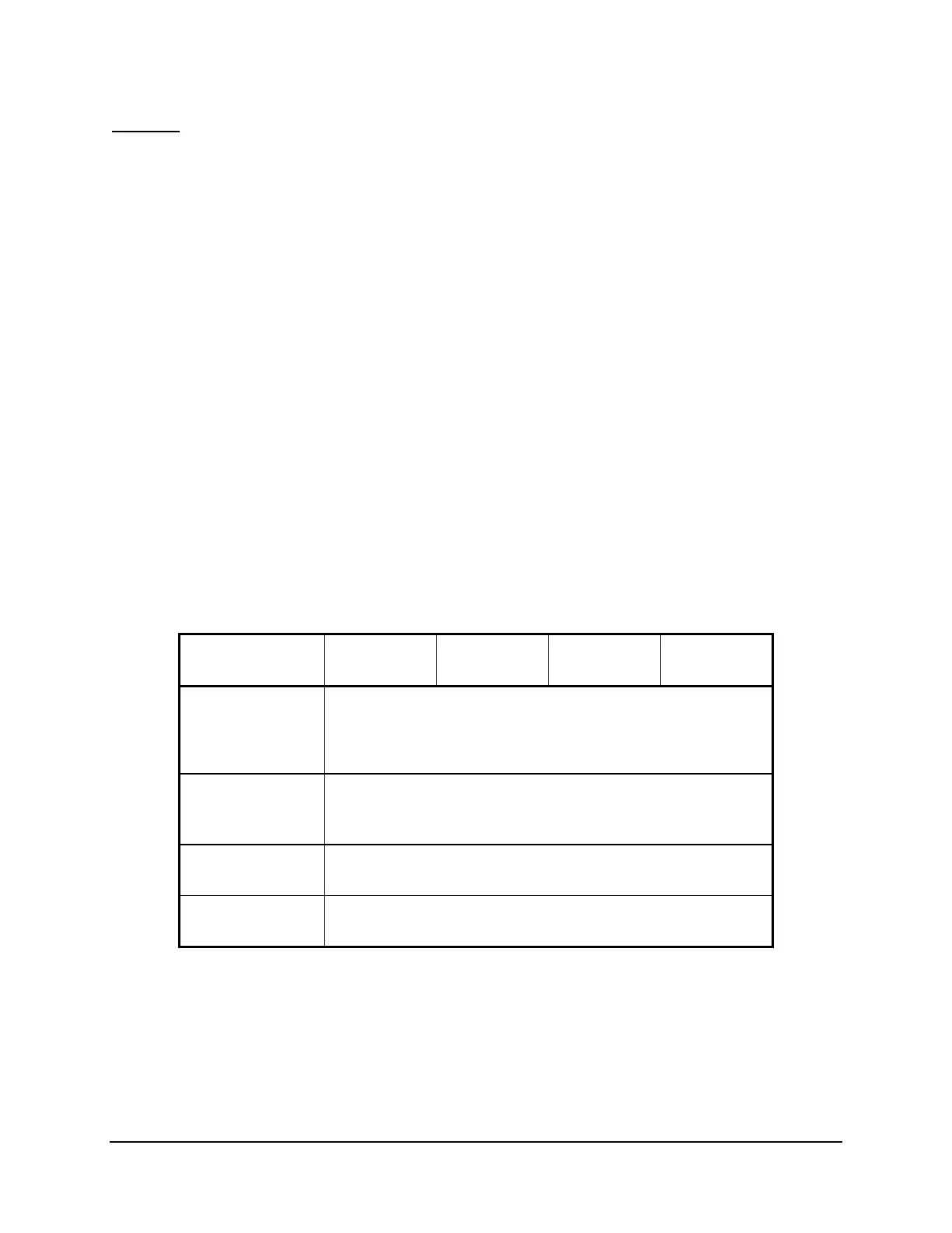
Table SECTION 4: .1: Overcurrent Elements Controlled by Level Direction Settings
DIR1 through DIR4 (corresponding overcurrent element figure numbers in parentheses)
Level Direction
Settings
Phase
Neutral
Ground
Residual
Ground
Negative-
Sequence
DIR1
67P1 (3.3)
67P1T (3.3)
51P1T (3.14)
51P2T (3.15)
67N1 (3.8)
67N1T (3.8)
51N1T (3.16)
51N2T (3.17)
67G1 (3.10)
67G1T (3.10)
51G1T (3.18)
51G2T (3.19)
67Q1 (3.12)
67Q1T (3.12)
51QT (3.20)
DIR2
67P2 (3.3)
67P2T (3.3)
67P2S (3.3)
67N2 (3.8)
67N2T (3.8)
67N2S (3.8)
67G2 (3.10)
67G2T (3.10)
67G2S (3.10)
67Q2 (3.12)
67Q2T (3.12)
67Q2S (3.12)
DIR3
67P3 (3.3)
67P3T (3.3)
67N3 (3.8)
67N3T (3.8)
67G3 (3.10)
67G3T (3.10)
67Q3 (3.12)
67Q3T (3.12)
DIR4
67P4 (3.3)
67P4T (3.3)
67N4 (3.8)
67N4T (3.8)
67G4 (3.10)
67G4T (3.10)
67Q4 (3.12)
67Q4T (3.12)
In most communications-assisted trip schemes, the levels are set as follows (see Figure 5.4):
Level 1 overcurrent elements set direction forward (DIR1 = F)
Level 2 overcurrent elements set direction forward (DIR2 = F)
Level 3 overcurrent elements set direction reverse (DIR3 = R)
In some applications, level direction settings DIR1 through DIR4 are not flexible enough in
assigning the desired direction for certain overcurrent elements. Subsection Directional Control