4-8 Loss-of-Potential, Load Encroachment, and Directional Element Logic Date Code 990430
SEL-351P Manual Técnico
DWG: M351R095a
Best Choice
Ground
Directional
Logic
Figure
4.8
neg.-seq.
volt.-pol.
Fig. 4.9
zero-seq.
volt.-pol.
residual
Fig. 4.10
Figure
4.5
Figure
4.12
Figure
4.6
32VE
50GR
"V" listed
in setting
ORDER
"Q" listed
in setting
ORDER
32QGE
50QR
R32V
Enables
Internal
50QF/
50GF/
F32V/
Figure
4.14
Level 2
Level 3
Level 4
to Residual Ground
Inst./Def.-Time
Overcurrent
Elements
Fig. 3.10
to Residual
Ground
Time-Overcurrent
Elements
Fig. 3.18
and 3.19
Figure
4.7
zero-seq.
volt.-pol.
neutral
Fig. 4.11
R32N
50NF/50NR
F32N/
Figure
4.13
Figure
4.15
Level 1
Level 2
Level 3
Level 4
to Neutral Ground
Inst./Def.-Time
OvercurrentElements
Fig. 3.8
to Neutral Ground
Time-Overcurrent
Elements
Fig. 3.16 and
3.17)
Control
Directional
Logic
Forward/
Reverse
Direction
Relay
Word Bit
Outputs
Routing
Element
Directional
Outputs
Word Bit
Relay
Directional
Elements
R32QG
F32QG/
32GR
32GF/
32NR
32NF/
Level 1
Word Bit
Outputs
Relay
ORDER
with Setting
Elements
Directional
Enable
™
32NE
disable
inputs
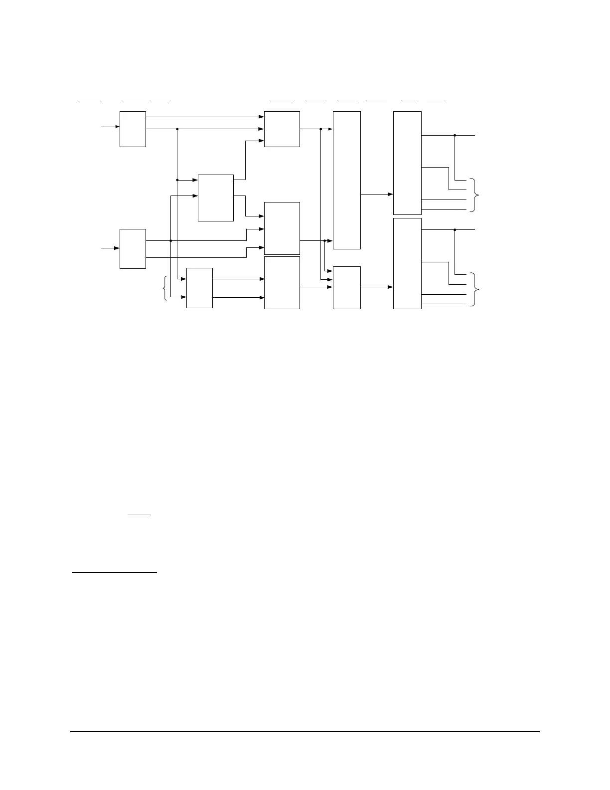
Figure SECTION 4: .4: General Logic Flow of Directional Control for Neutral
Ground and Residual Ground Overcurrent Elements
Figure SECTION 4: .4 gives an overview of how these directional elements are enabled and
routed to control the neutral ground and residual ground overcurrent elements.
Note in
Figure SECTION 4: .4 that setting ORDER enables the directional elements. Setting
ORDER can be set with any combination of Q and V. They have the following correspondence
to the directional elements:
Q Negative-sequence voltage-polarized directional element
V Zero-sequence voltage-polarized, residual-current directional element and
zero-sequence voltage-polarized, neutral-current directional element
The order
in which these directional elements are listed in setting ORDER determines the
priority in which they operate to provide Best Choice Ground Directional™ logic control. See
discussion on setting ORDER in the following subsection Directional Control Settings.
Internal Enables
Refer to
Figure SECTION 4: .4, Figure SECTION 4: .5, Figure SECTION 4: .6, and
Figure SECTION 4: .7.
The internal enables 32QGE and 32VE have the following correspondence to the directional
elements:
32QGE Negative-sequence voltage-polarized directional element
32VE Zero-sequence voltage-polarized, residual-current directional element and
zero-sequence voltage-polarized, neutral-current directional element