Date Code 990215 Trip and Target Logic 5-27
SEL-351P Manual Técnico
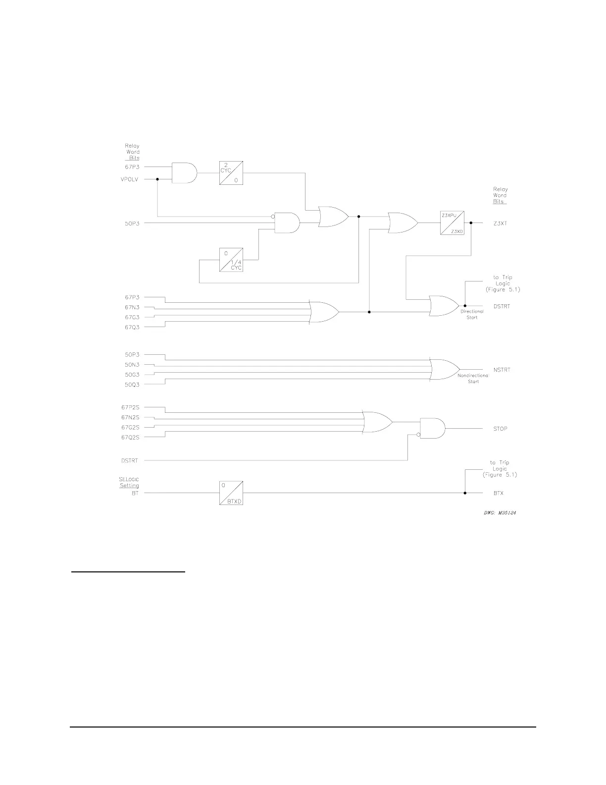
BTX – Block Trip Extension
The received block trip input (e.g., BT = IN104) is routed through a dropout timer (BTXD) in the
DCB logic in
Figure SECTION 5: .14. The timer output (BTX) is routed to the trip logic in
Figure SECTION 5: .1.
Figure SECTION 5: .14: DCB Logic
Installation Variations
Figure SECTION 5: .16 shows output contacts OUT104, OUT105, OUT106, and OUT107
connected to separate communications equipment for the two remote terminals. Both output
contact pairs are programmed the same (OUT105 = DSTRT + NSTRT and
OUT107 = DSTRT + NSTRT; OUT106 = STOP and OUT104 = STOP).
Depending on the installation, perhaps one output contact (e.g., OUT105 = DSTRT + NSTRT)
can be connected in parallel to both START inputs on the communications equipment in
Figure
SECTION 5: .16. Then output contact OUT107 can be used for another function.