7-2 Inputs, Outputs, Timers, and Other Control Logic Date Code 990215
SEL-351P Manual Técnico
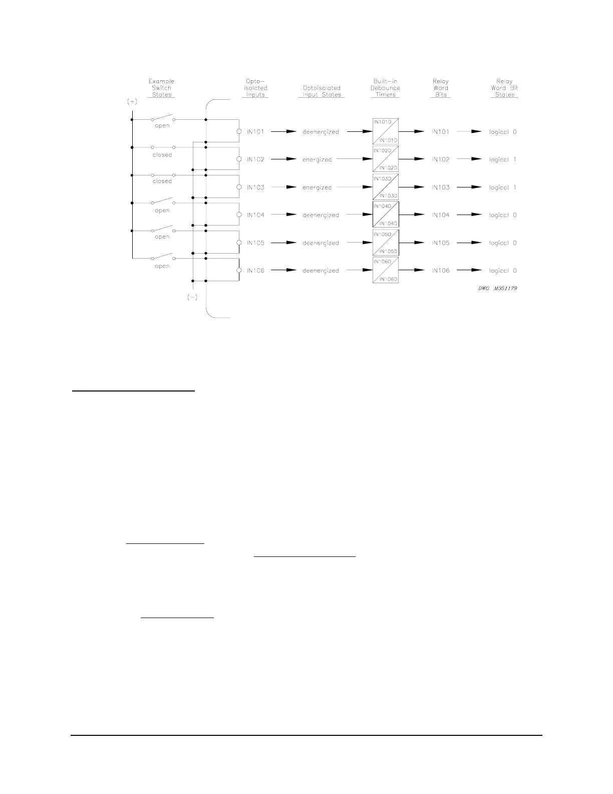
Figure SECTION 7: .1: Example Operation of Optoisolated Inputs IN101 Through
IN106
Input Debounce Timers
See
Figure SECTION 7: .1.
Each input has settable pickup/dropout timers (IN101D through IN106D) for input
energization/deenergization debounce. Note that a given time setting (e.g., IN101D = 0.50) is
applied to both the pickup and dropout time for the corresponding input.
Time settings IN101D through IN106D are settable from 0.00 to 1.00 cycles. The SEL-351P
takes the entered time setting and internally runs the timer at the nearest 1/16-cycle. For
example, if setting IN5D = 0.80, internally the timer runs at the nearest 1/16-cycle: 13/16-cycles
(13/16 = 0.8125).
For most applications
, the input pickup/dropout debounce timers should be set in 1/4-cycle
increments. For example, in the factory default settings
, all the optoisolated input
pickup/dropout debounce timers are set at 1/2-cycle (e.g., IN104D = 0.50). See SHO Command
(Show/View Settings) in Section 10: Serial Port Communications and Commands for a list of
the factory default settings.
Only a few applications
(e.g., communications-assisted tripping schemes) might require input
pickup/dropout debounce timers set less than 1/4-cycle [e.g., if setting IN105D = 0.13, internally
the timer runs at the nearest 1/16-cycle: 2/16-cycles (2/16 = 0.1250)].
The relay processing interval is 1/4-cycle, so Relay Word bits IN101 through IN106 are updated
every 1/4-cycle. The optoisolated input status may have made it through the pickup/dropout
debounce timer (for settings less than 1/4-cycle) because these timers run each 1/16-cycle, but
Relay Word bits IN101 through IN106 are updated every 1/4-cycle.