3-34 Overcurrent, Voltage, Synchronism Check, and Frequency Elements Date Code 990430
SEL-351P Manual Técnico
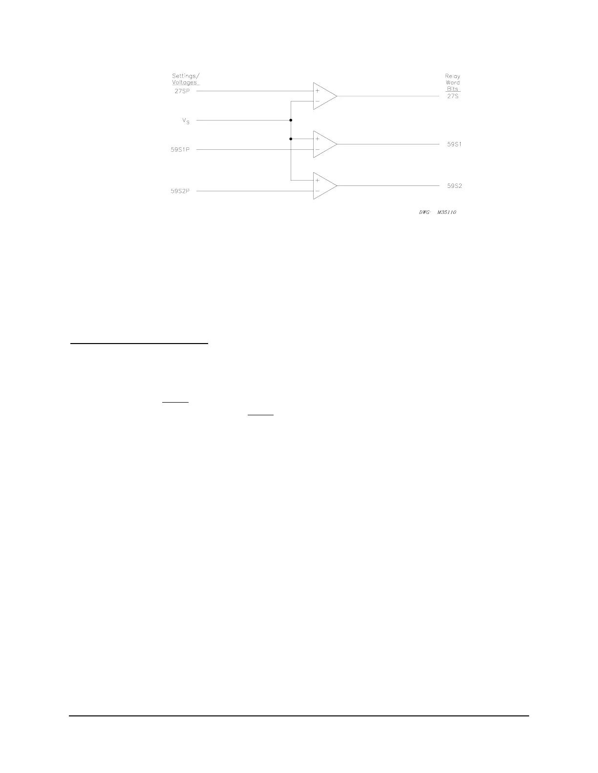
Figure SECTION 3: .23: Channel VS Voltage Elements
Accuracy
Pickup: ±1 V and ±5% of setting
Transient Overreach: ±5% of setting
Voltage Element Operation
Note that the voltage elements in
Table SECTION 3: .8, Figure SECTION 3: .21 and
Figure SECTION 3: .22 are a combination of “undervoltage” (Device 27) and “overvoltage”
(Device 59) type elements. Undervoltage elements (Device 27) assert when the operating
voltage goes below
the corresponding pickup setting. Overvoltage elements (Device 59) assert
when the operating voltage goes above
the corresponding pickup setting.
Undervoltage Element Operation Example
Refer to
Figure SECTION 3: .21 (top of the figure).
Pickup setting 27P1P is compared to the magnitudes of the individual phase voltages V
A
, V
B
, and
V
C
. The logic outputs in Figure SECTION 3: .21 are the following Relay Word bits:
27A1 = 1 (logical 1), if V
A
< pickup setting 27P1P
= 0 (logical 0), if V
A
≥ pickup setting 27P1P
27B1 = 1 (logical 1), if VB < pickup setting 27P1P
= 0 (logical 0), if VB ≥ pickup setting 27P1P
27C1 = 1 (logical 1), if VC < pickup setting 27P1P
= 0 (logical 0), if VC ≥ pickup setting 27P1P
3P27 = 1 (logical 1), if all three Relay Word bits 27A1, 27B1, and 27C1 are asserted
(27A1 = 1, 27B1 = 1, and 27C1 = 1)
= 0 (logical 0), if at least one of the Relay Word bits 27A1, 27B1, or 27C1 is
deasserted (e.g., 27A1 = 0)