4-6 Loss-of-Potential, Load Encroachment, and Directional Element Logic Date Code 990430
SEL-351P Manual Técnico
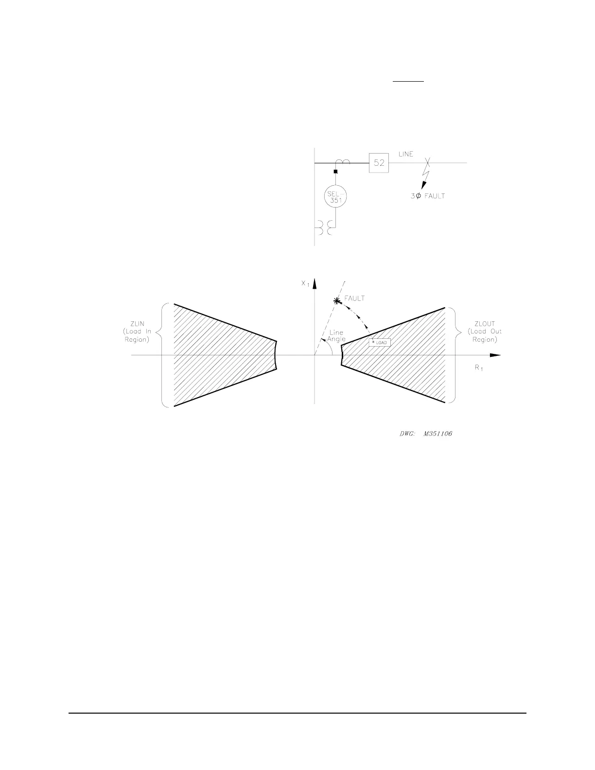
If a fault occurs, the apparent positive-sequence impedance moves outside the ZLOUT area (and
stays outside the ZLIN area, too), resulting in :
ZLOAD = ZLOUT + ZLIN = logical 0 + logical 0 = logical 0
Figure SECTION 4: .3: Migration of Apparent Positive-Sequence Impedance for a
Fault Condition
Refer to Figure 3.14 in Section 3: Overcurrent, Voltage, Synchronism Check, and Frequency
Elements. To prevent phase time-overcurrent element 51P1T from operating for high load
conditions, make the following SEL
OGIC
®
Control Equation torque control setting:
51P1TC = !ZLOAD*!LOP + 50P6 (= NOT[ZLOAD]*NOT[LOP] + 50P6)
As shown in
Figure SECTION 4: .2, load-encroachment logic is a positive-sequence calculation.
During LOP conditions (loss-of-potential; see
Figure SECTION 4: .1), positive-sequence voltage
(V
1
) can be substantially depressed in magnitude or changed in angle. This change in V
1
can
possibly cause ZLOAD to deassert (= logical 0), erroneously indicating that a “fault condition”
exists. Thus, !ZLOAD should be supervised by !LOP in a torque control setting. This also
effectively happens in the directional element in
Figure SECTION 4: .18, where ZLOAD and
LOP are part of the logic.
In the above setting example, phase instantaneous overcurrent element 50P6 is set above any
maximum load current level - if 50P6 picks up, there is assuredly a fault. For faults below the
pickup level of 50P6, but above the pickup of phase time-overcurrent element 51PT, the