EasyManua.ls Logo

SICK FLOWSIC100 Flare-XT - Page 183

SICK FLOWSIC100 Flare-XT
188 pages
Print Icon
To Next Page IconTo Next Page
To Previous Page IconTo Previous Page
Loading...
Annex
FLOWSIC100 Flare-XT · Operating Instructions · 8023761/V 1-0/2020-10 · © SICK Engineering GmbH 183
Fig. 116 Control Drawings FLSE-XT (page 4 of 5)
Date
Created
Date
Released
FLARE-XT CONTROL DRAWING
2020-09-23
scheisv
2020-09-28
scheisv
FLARE-XT CONTROL DRAWING
Type:
Ident No: E288088
Rev.
Date
Name
D-01458 Ottendorf-Okrilla
Repl. for:
Repl. by:
Sh. 4 / 5
?
04
FLOWSIC100-XT-S/-R/-M
Class I, Division 1, Groups B, C and D, T4
Class I, Zone 1, Ex/AEx d[ia] IIB + H2, T4
Class I, Division 2, Groups A, B, C and D, T4
Class I, Zone 2, Ex/AEx nA[ia] IIC, T4
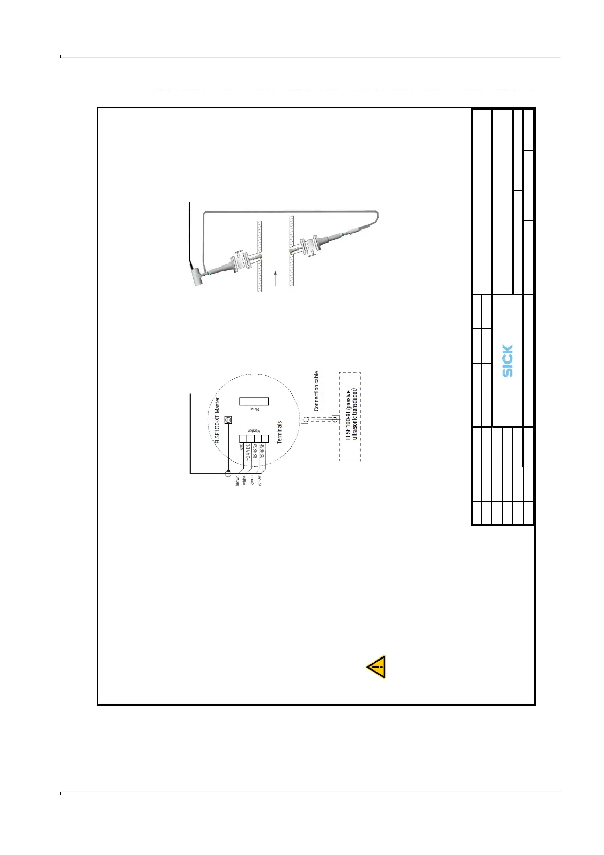
Power Supply:
Terminals +24 V, GND
15…28 VDC, max. 500 mA
Data Interface:
Terminals RS485a, RS485b
±5 V, max. 500 mA
Install device in accordance with NEC (ANSI/NFPA 70 ) in USA or CEC Part 1 in Canada.
“[Ex ia]”
WARNING: Substitution of components may impair intrinsic safety.
AVERTISSEMENT: La substitution de composants peut nuire à la sécurité intrinsèque.
Maximum non-hazardous voltage not to exceed 125 V.
La tension maximale non dangereuse ne doit pas dépasser 125 V
Flameproof field wiring
Connecting Diagram Installation Diagram
Flameproof field wiring
Intrinsically safe
transducer
wiring
Zone separating wall
e. g. pip
e
line or duct

Table of Contents

Related product manuals