Installation
MCS100E Operating Instructions 8009504/VYWA7/V3-1/2018-01 © SICK AG 31
Subject to change without notice
3.3.2 Modem with the NetOP program
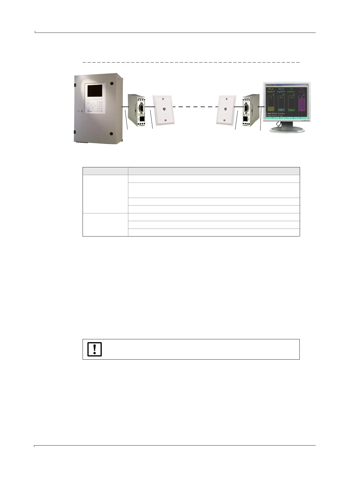
Figure 11 Remote control via modem
Equipment
3.3.2.1 Connection on MCS100E side
1 Connect the RS232C interface of MCS100E (
→
p. 28, Figure 8) to the modem.
The modem setting cannot be changed.
2 Connect the modem to the telephone network (analog).
3.3.2.2 Connection on PC side
1 Connect the modem to the telephone network (analog).
– If an external modem is used (this means: No modem PC card):
Connection of modem exclusively to a “real” COM port of the PC
- No USB ports
- No USB-to-COM ports
2 Set the modem corresponding to the PC.
3.3.2.3 Program start on MCS100E side
1 Start MCS100E.
2 If NetOP has not been pre-installed:
– Copy directory \ndial to the root directory of MCS100E
– Check BIOS settings:
- COM port: COM 4 or AUTO
- COM port may not be occupied already.
MCS100E
RS232
RS232
Telephone line
Telephone line
PC
Modem ModemTelephone connection Telephone connection
Control unit Equipment
MCS100E side
RS232 interface for MCS100E ((Part No. 2023049)
Modem (Part No. 6029430)
Power supply unit 100 - 240 V, 24 V) (Part No. 6029654)
NetOP software (pre-installed)
Telephone connection (analog)
PC side
Telephone connection (analog)
Modem
NetOP software (Part No. 6029452).
If NetOP has not been installed:
Leave the installation of NetOP to an expert.