Product description
MCS100E Operating Instructions 8009504/VYWA7/V3-1/2018-01 © SICK AG 17
Subject to change without notice
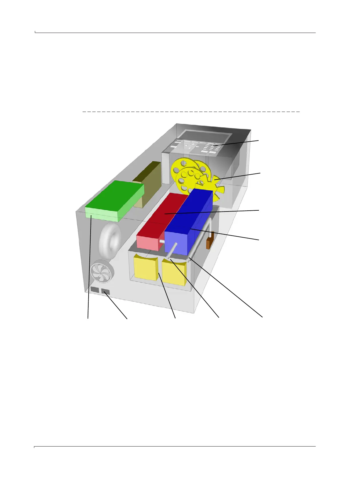
2.2.1 Design
MCS100E consists of the following main assemblies:
• Photometer with filter wheels (design dependent on application)
• Cell (optical path length dependent on application)
• Flow meter
•O
2
sensor (optional)
• Computer and electronics
Figure 2 MCS100E setup
Computer
Flow meter
Photometer
User interface
Interfaces
Cell
Sample gas outlet
Sample gas inlet
O
2
sensor
(optional)