Operation
MCS100E Operating Instructions 8009504/VYWA7/V3-1/2018-01 © SICK AG 79
Subject to change without notice
5.7.11.8 Definition of Components
Specialist: System edit: Definition of Components
As a default setting the results 1..24 correspond to the components 1..24. Linearization
and interference tables can be applied to these results.
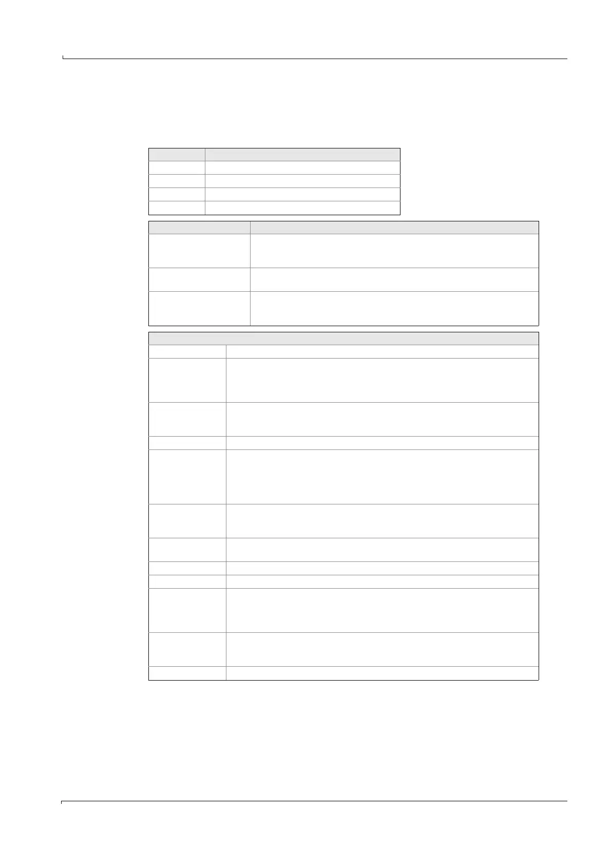
Result Default setting
01..14 Sample components 1..14
15 Flow meter
16 O
2
sensor
17..24 Analog inputs channel 1..8 (I/O module boxes)
Setting Meaning
Is there an aperture at
position 8 of filter wheel 1
Yes: MCS100E avoids a filter wheel position where there are 2 subsequent
empty apertures (overload of detector) by first positioning filter wheel 2 on a
filter and then filter wheel 1 on an empty aperture.
If filter wheel 3 is used for
calibration
Yes: Filter wheel 3 is moved to the corresponding filter during calibration of
one component.
Wait time until start
of integration
Waiting time from swinging in the measurement filter until start of
measurement (valid for ALL components).
Standard value: 125 ms.
Settings
No. Number i equals component i
active Mark = active () (valid for i = 1..16)
Analog inputs always automatically have a mark, as soon as an I/O module box with
analog inputs is connected.
The marks have to be set for the flow meter (K15) and O
2
sensor (K16).
Name A list is displayed (based on Specialist: System edit: Results). The name of the
component that is to be measured can be seen.
Default setting is: Result number = Component number.
Unit Displayed automatically from “Specialist: System edit: Results“
Measurement per
cycle
Defines how often (1..9 times) the component is to be measured within one cycle.
Subsequently, the cycle time is calculated.
“0” means: This component will not be measured.
Note: The components are measured one after the other, no other components are
measured in between.
Time [ms] wait Wait time until start of measurement for Reference signal (sample filter see below)
in ms. Default values are presented, scroll with <ENTER>.
Standard value: 125 ms.
Time [ms] integ. Integration time in ms.
Default values are presented, scroll with <ENTER>. Standard value: 500 ms.
Reference signal Position of reference filters
Measuring signal Position of sample filters
F1, F2, F3 Filter wheel 1, 2, 3. Usually:
F1: Interference filter
F2: Gas filter
F3: Span gas filter or internal standard
Gi i = amplifier level (i = 1..19)
Enter amplifier level manually. For automatic setting go to: Specialist: Utilities:
Service: Control Detector unit Tst5 (Gain calculation).
T90 T90 time (0..1200 sec.). Floating mean value.