Installation
26 MCS100E Operating Instructions 8009504/VYWA7/V3-1/2018-01 © SICK AG
Subject to change without notice
3.2.3 Interfaces
3.2.3.1 Optical interfaces
The optical connections are located at the bottom of MCS100E.
Connecting the fiber optical cables:
⊗ Do not sharply bend the fiber optical cables.
• Minimum bending radius: 3 cm.
• The direction of the fiber optical cable can be as desired.
• The connectors can be plugged into the sockets in any 90° angle.
Press connector into socket until you hear that it is locked.
To remove the fiber optical cables, pull at the connector only (not at the cable).
Optical interface “module box“
I/O module boxes (digital and analog input/output units) or HC8X heating controllers are
connected to the interface to the “module box”.
• Max. length of recommended fiber optical cables: 50 m (for further information, refer to
Technical Data).
• Designation of the connections:
– At the MCS100E: Module box “E” or “S”
– At the module box:“MA E” or “MA S”
(MA = Master, E = Receiver, S = Sender)
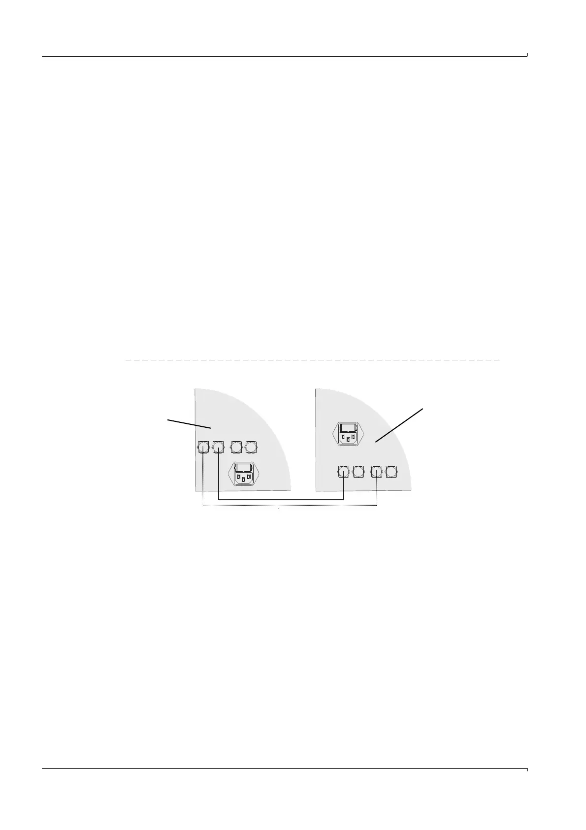
Figure 5 Connection of “module box” interface
MA SL MA SL
E E S S
E S E S
I/O module box or HC8X
“MA” interfaces
MCS100E
“Module box” interfaces