E3G060 Control module ”monitored” (Part No 542539)
145
Building Technologies 001260_k_en_--.doc
Fire Safety & Security Products 02.2005
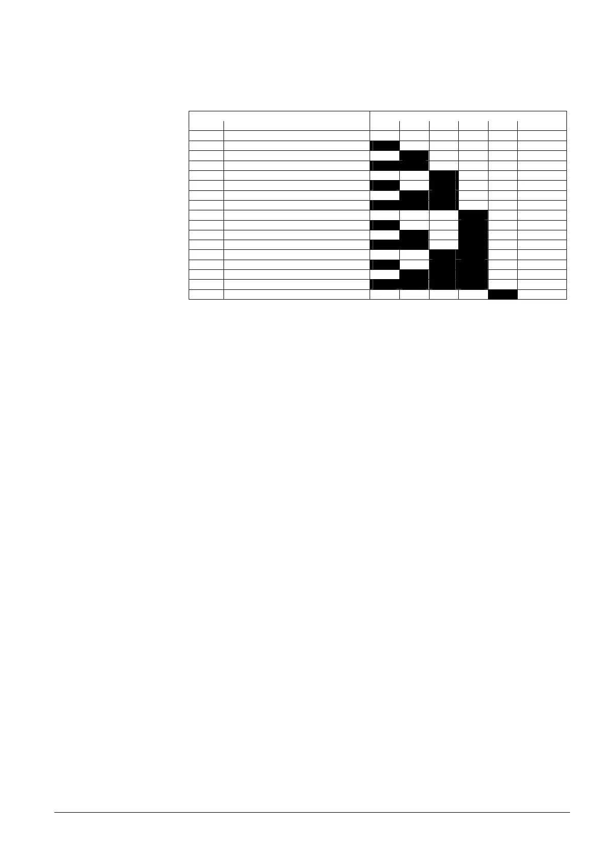
3 Programming switch "S3": "I-Bus address" setting
Each element (module) connected to I-Bus must have an individual address (number).
This is set on programming switch "S3".
Maximum 16 I-Bus devices.
Function / I-Bus address Programming switch S3
Nr. S3-1 S3-2 S3-3 S3-4 S3-5 S3-6
0 Module out of commission (unused) off off off off off off
1 I-Bus user number 1 on off off off off off
2 2 off on off off off off
3 3 on on off off off off
4 4 off off on off off off
5 5 on off on off off off
6 6 off on on off off off
7 7 on on on off off off
8 8 off off off on off off
9 9 on off off on off off
10 10 off on off on off off
11 11 on on off on off off
12 12 off off on on off off
13 13 on off on on off off
14 14 off on on on off off
15 15 on on on on off off
16 16 off off off off on off
"S3-1...6" are set to "off" at the factory
4 Flachband-Header "ST1" (26-polig): I-Bus
5 0 Ω resistor: no function (factory setting X11)
6 Maintenance switch "S2": To switch on maintenance LEDs for test purposes.
In addition to the control line, it also enables the activation of the correspond-
ing LED (H1...H6).
S2-on = LED (H1..H6) lights if the control line is activated.
7 Plug-in terminals "K2": to synchronize Horns or external oscillator input
8 Plug-in terminals "K1": Supply for "I-Bus" modules
9 Plug-in terminals "K3": External horn supply
10 Fuse: 'F19' 6.3 A/T for internal module and horn if internal supply (K1)
11 0 Ω resistor: Supply for 6 horn outputs (X1-2..14)
X12 = internal supply (factory setting) (K1)
Y12 = external supply (K3)
12 Fuses: 'F1, F3, F5, F7, F9, F11' 2 A/T Control lines monitored (Fuses with
high breaking capacity, sand-filled)
13 Test LEDs 'H1...H6' at rear allocation of the individual LEDs H1...H6 –> see
page 146

 Loading...


