8 Using the Data Record Interface
139
IE/AS−INTERFACE LINK PN IO as of hardware version 1, as of firmware version V2.0
Release 08/2018
C79000−G8976−C216−03
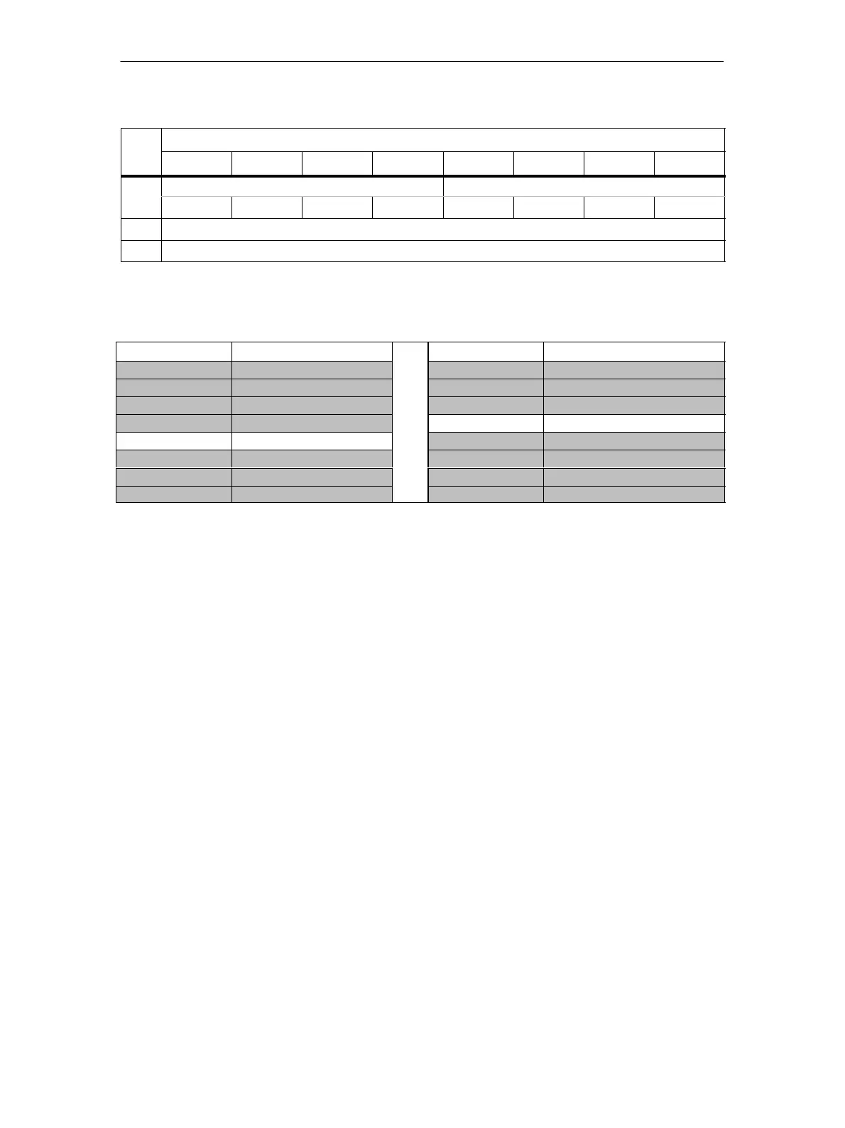
Byte Meaning
Bit 0Bit 1Bit 2Bit 3Bit 4Bit 5Bit 6Bit 7
Parameter 30/30B Parameter 31/31B
169
P3 P2 P1 P0 P3 P2 P1 P0
170 Flag 1
171 Flag 2
Flag 1 Flag 2
Bit Number Meaning Bit Number Meaning
0 CONFIG_OK 0 PERIPHERY_OK
1 LDS_0 1 DATA_EXCHANGE_ACTIVE
2 AUTO_ADDR_ASSIGN 2 OFFLINE
3 AUTO_ADDR_AVAIL 3 AUTO_ADDR_ENABLE
4 CONFIG_MODE 4 Ground short
5 NORMAL_MODE 5 EPROM_OK
6 APF 6 reserved
7 OFFLINE_READY 7 reserved
In the table, the rows of the flags whose values change the mode of the AS-i
master (CONFIG_MODE, AUTO_ADDR_ENABLE) are shown in white.
The values of the other flags (gray in the table) have no significance for the
’Set_LPS_PCD_PP_Flags’ call and cannot be modified on the AS-i master with
this call..
The meaning of the flags is the same as in the “Get_LPS_LAS_LDS_LPF_Flags”
job, Section 8.2.1.4).

 Loading...