1 Technical Description, Installation Guidelines, Operation
21
IE/AS−INTERFACE LINK PN IO as of hardware version 1, as of firmware version V2.0
Release 08/2018
C79000−G8976−C216−03
1.7.1 Connectors for the AS-i Cable(s) and Power Supply
!
Caution
When connecting up the module, keep to the installation guidelines in Section 1.5.
!
Caution
The IE/AS-INTERFACE LINK PN IO may only be connected when the AS-i power
supply unit is turned off.
Connectors for the AS-i Cable(s)
The IE/AS-i LINK has two connectors for the AS-i cables (line 1 and line 2). Each
is connected over a 4-pin plug with two + and two − contacts that are jumpered
internally.
This allows the IE/AS-i LINK to be looped into the AS-i cable.
!
Caution
The permitted current loading of the AS-i connection contacts is 3 A. If this value
is exceeded on the AS-i cable, the IE/AS-INTERFACE LINK PN IO must not be
looped into the AS-i cable but must be connected with a tap line (only one pair of
connectors of the IE/AS-i LINK is used).
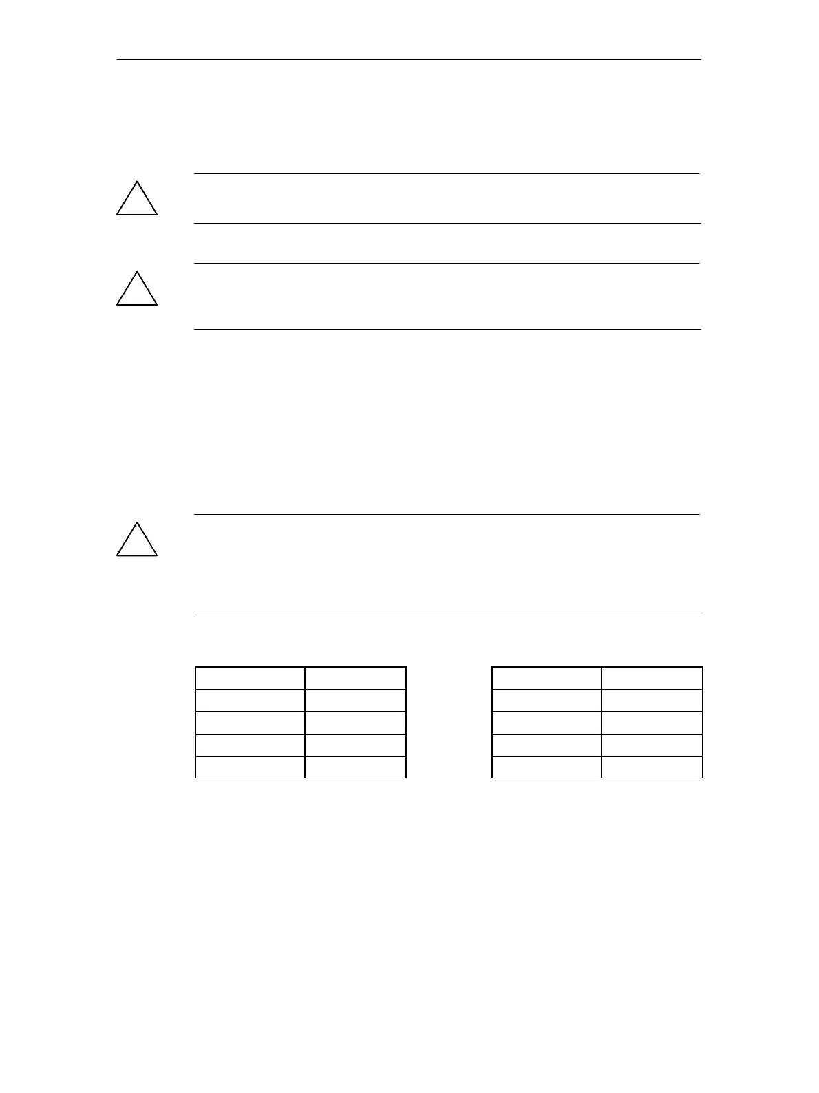
Pin assignment of the AS-i line
PIN no. line 1 Signal
1 AS-i 1 +
2 AS-i 1 −
3 AS-i 1 +
4 AS-i 1 −
PIN no. line 2 Signal
1 AS-i 2 +
2 AS-i 2 −
3 AS-i 2 +
4 AS-i 2 −
Pins 1 and 3 and pins 2 and 4 are jumpered internally.

 Loading...