Programming
10.2 Positional data
Surface grinding
212 Programming and Operating Manual, 11/2012, 6FC5398-5CP10-3BA0
10.2.3 Absolute/incremental dimensioning: G90, G91, AC, IC
Functionality
With the instructions G90/G91, the written positional data X, Y, Z, ... are evaluated as a
coordinate point (G90) or as an axis position to traverse to (G91). G90/G91 applies to all
axes.
Irrespective of G90/G91, certain positional data can be specified for certain blocks in
absolute/incremental dimensions using AC/IC.
These instructions do not determine the path by which the end points are reached; this is
provided by a G group (G0, G1, G2 and G3... see Chapter "Axis Movements").
Programming
G90 ; Absolute dimension data
G91 ; Incremental dimension data
X=AC(...) ; Absolute dimensioning for a certain axis (here: X axis), non-modal
X=IC(...) ; Absolute dimensioning for a certain axis (here: X axis), non-modal
3
<
3
3
;
3
<
3
3
;
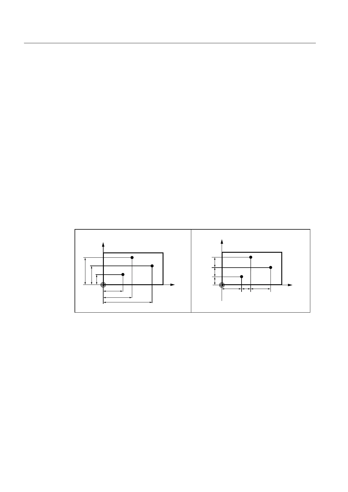
,QFUHPHQWDOGLPHQVLRQ
$EVROXWHGLPHQVLRQV
Figure 10-4 Different dimensioning types in the drawing
Absolute dimensioning G90
With absolute dimensioning, the dimensioning data refers to the zero of the coordinate
system currently active (workpiece or current workpiece coordinate system or machine
coordinate system). This is dependent on which offsets are currently active: programmable,
settable, or no offsets.
Upon program start, G90 is active for all axes and remains active until it is deselected in a
subsequent block by G91 (incremental dimensioning data) (modally active).
Incremental dimensioning G91
With incremental dimensioning, the numerical value of the path information corresponds to
the axis path to be traversed. The leading sign indicates the traversing direction.