Description
1.5 Coordinate systems
Surface grinding
16 Programming and Operating Manual, 11/2012, 6FC5398-5CP10-3BA0
Note
This documentation assumes an 802D standard machine control panel (MCP). Should you
use a different MCP, the operation may be other than described herein.
1.5 Coordinate systems
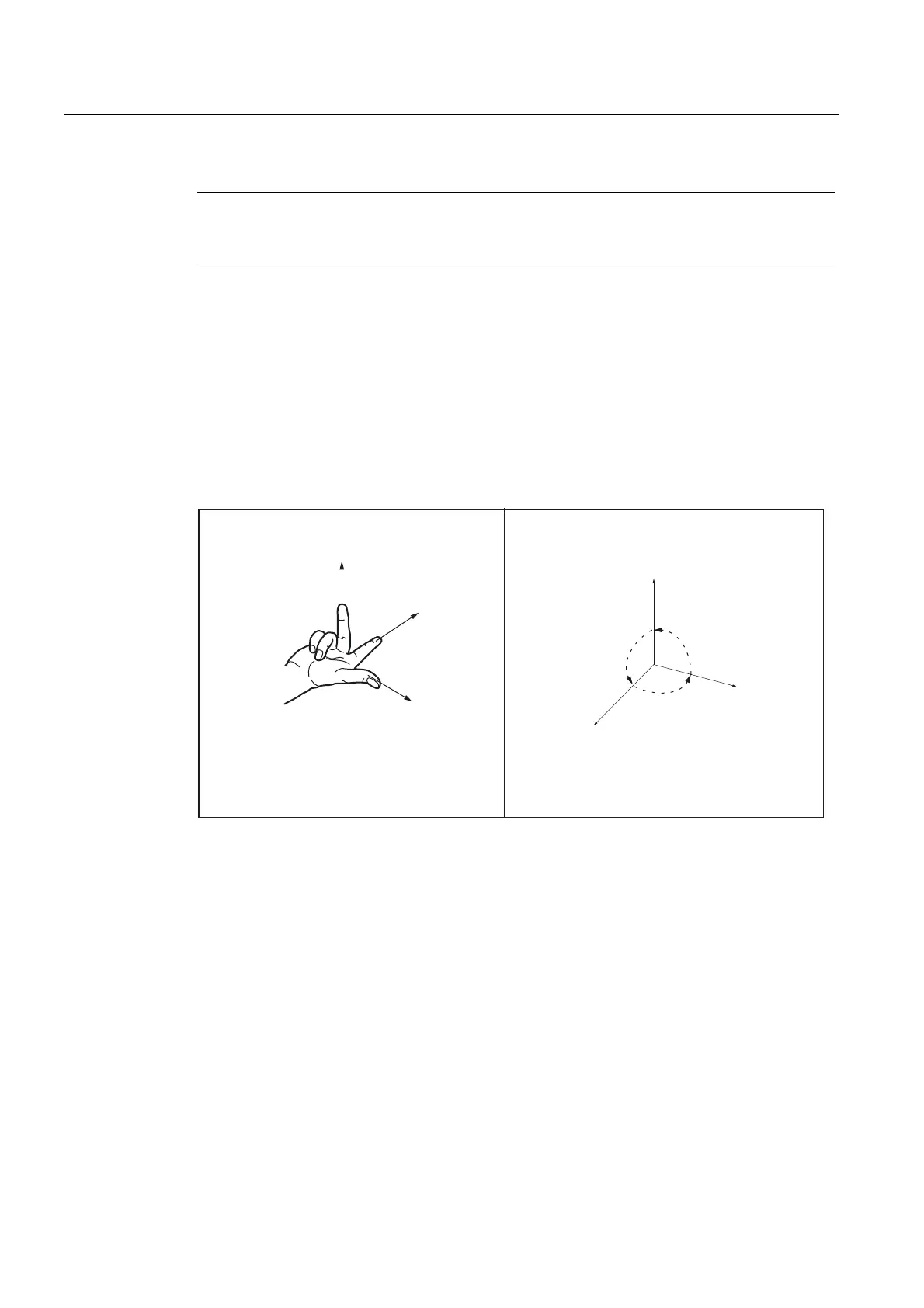
As a rule, a coordinate system is formed from three mutually perpendicular coordinate axes.
The positive directions of the coordinate axes are defined using the so-called "3-finger rule"
of the right hand. The coordinate system is related to the workpiece and programming takes
place independently of whether the tool or the workpiece is being traversed. When
programming, it is always assumed that the tool traverses relative to the coordinate system
of the workpiece, which is intended to be stationary.
90°
90°
90°
;
=
<
;
=
<
Figure 1-2 Determination of the axis directions to one another; coordinate system for programming
Machine coordinate system (MCS)
The orientation of the coordinate system relative to the machine depends on the respective
machine type. It can be rotated in different positions.
The directions of the axes follow the "3-finger rule" of the right hand. Seen from in front of the
machine, the middle finger of the right hand points in the opposite direction to the infeed of
the main spindle.