Programming
10.3 Axis movements
Surface grinding
Programming and Operating Manual, 11/2012, 6FC5398-5CP10-3BA0
229
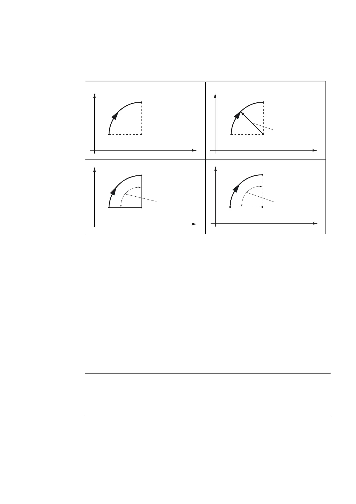
The description of the desired circle can be given in various ways:
(QGSRLQW;<
$QJOH$5
HJ*$5 ;<
<
;
6WDUWLQJSRLQW;<
**DQGDSHUWXUHDQJOHVSHFLILFDWLRQHQGSRLQW
&HQWHUSRLQW,-
HJ*$5 ,-
<
;
6WDUWLQJSRLQW;<
HJ*;<&5 HJ*;<,-
&LUFOHUDGLXV&5
<
;
6WDUWLQJSRLQW;<
(QGSRLQW;<
<
;
&HQWHUSRLQW,-
6WDUWLQJSRLQW;<
(QGSRLQW;<
**DQGDSHUWXUHDQJOHVSHFLILFDWLRQFHQWHUSRLQW
**DQGUDGLXVSDUDPHWHUHQGSRLQW**DQGFHQWHUSRLQWSDUDPHWHUHQGSRLQW
$QJOH$5
Figure 10-16 Possibilities of circle programming with G2/G3 using the example of the axes X/Y and
G2
G2/G3 remains active until canceled by another instruction from this G group (G0, G1, ...).
The path velocity is determined by the programmed F word.
Programming
G2/G3 X... Y... I... J... ; Center and end point
G2/G3 CR=... X... Y... ; Circle radius and end point
G2/G3 AR=... I... J... ; Opening angle and center point
G2/G3 AR=... X... Y... ; Opening angle and end point
G2/G3 AP=... RP=... ; Polar coordinates, circle around the pole
Note
Further possibilities for circle programming result from:
CT - circle with tangential connection and
CIP - circle via intermediate point (see next sections).